Rectifier

Status
Not open for further replies.
Joined
Aug 9, 2009
Messages
128
Country flag
Tell me what you think, I would say that looks like a Full wave Bridge Rectifier using Zeners. Not a half wave. My Bike has a full wave rectifier and the double zeners. its not an issue as the bike runs and charges just fine. However I don't really like it. Just a point of interest

Rectifier
 
I don't see a lot of difference between the two in the mode of operation.
You may as well not have the diodes across the zener in the second version as the zener will act like a diode in the forward conduction condition and as an avalanche diode (zener) in the reverse bias condition.

Also I will have to have a think about the final regulated voltage output as I'm sure it be .7v lower than the zener voltage due to the forward voltage drop of the diode between the zener and the negative output.

I'm happy to be wrong about the whole comment also I would be putting the zener on the output (negative batt) feed, this way the charge voltage will be the zener voltage.
Or use a zener with a higher regulation voltage.

Cheers
and all the best for xmas
Peter R
 
Any of those drawings will work. The final drawing of your Norton has redundant regular diodes in parallel with the Zener diodes. The circuit will act the same as if the redundant regular diodes were not there.

It is obvious that someone has replaced the original selenium rectifier with a full wave bridge -most likely a silicone rectifier- The fact that it is a silicone diode will reduce the voltage by about .7 volt.
That is not a big deal, all the replacement rectifier/regulators available [podtronics,ect] use silicone diodes in place of selenium. Jim
 
Just a by note that might be of interest to some.
I have seen electronic regulators that use SCR's instead of the zeners or diodes in the bottom half of the bridge rectifier.
They then pulse width modulate the gate of the SCR against a voltage reference (simple ones use a small zener) and the terminal battery voltage to give the desired regulated output.
Quite sneaky as the SCR will drop out of conduction on each reverse voltage cycle.

Peter R
 
bluemax said:
Just a by note that might be of interest to some.
I have seen electronic regulators that use SCR's instead of the zeners or diodes in the bottom half of the bridge rectifier.
They then pulse width modulate the gate of the SCR against a voltage reference (simple ones use a small zener) and the terminal battery voltage to give the desired regulated output.
Quite sneaky as the SCR will drop out of conduction on each reverse voltage cycle.

Peter R

Yes,but all the units I have seen are still a shunt regulator though. Excess voltage is shunted to ground and the alternator is always running at full capacity.

There are a couple series regulators available now that do unload the alternator instead of shunting the output. They are rather expensive and there is little to gain with a low output alternator such as a Norton alternator.

I recently installed a series regulator on my bike because I have a 38 amp alternator that was overkill most of the time. It dropped the stator temp by a large margin and freed up about 1 1/2 horse at 4000 rpm [as long as I am not using my driving lights and electric gear]. Jim
 
Yes Jim I agree not much of consequence for the feeble Norton alternator but shunt regulators on high output system it would need some serious heat sinks or run with all the load on.
My previous comment just reminded me of one I had on my Norton that I de potted to see how it worked and the diagram in the original post reminded me of it.
Without trying to hijack the post (I think he has the answer he was after) the one I de potted was fitted to a positive earth system, can you pick the obvious problem?
It left me stranded miles from home until tweaked to the problem the PO had left me with.
Rectifier


Cheers
Peter R
 
comnoz said:
It is obvious that someone has replaced the original selenium rectifier with a full wave bridge -most likely a silicone rectifier-

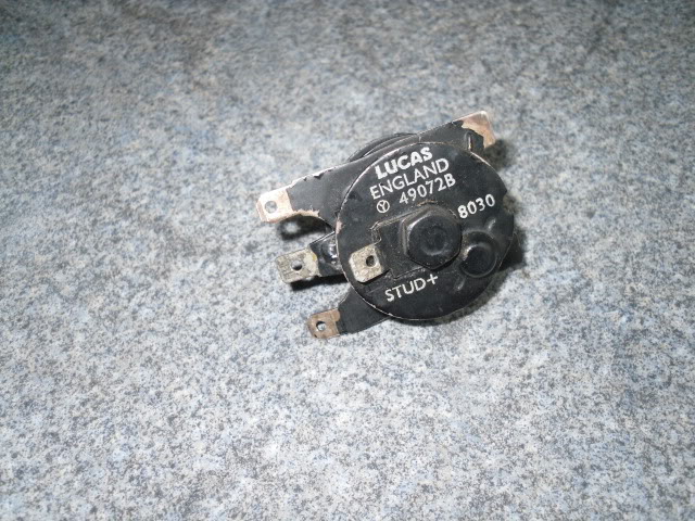
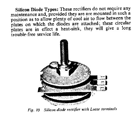
The standard Lucas multi-plate rectifiers as fitted to motorcycles from around 1963 onwards in both four and two (850 MkIII) diode forms are silicon not selenium.
Rectifier

Manual
Rectifier
 
Yes,but all the units I have seen are still a shunt regulator though. Excess voltage is shunted to ground and the alternator is always running at full capacity.

There are a couple series regulators available now that do unload the alternator instead of shunting the output. They are rather expensive and there is little to gain with a low output alternator such as a Norton alternator.

Jim you might very well be right but from a comment I got when I wrote to Podtronics a while back leads me to believe me that they may not be shunt regulators.
I would not consider Podtronic rectifier/regulator as expensive would you.

I had some queries about how the Podtronics rectifier/regulator handled certain situations like an open circuit battery or load and part of their reply was

...."The Podtronics will actually go "low" if it does not see a load. The load is usually a battery, however it can also be a headlight." ...

To do this my gut feeling tell me it is not a shunt regulator and more like the one I described earlier.
Has anyone ever felt the temp of a podtronics with engine running with no load and then with full load.
If it get cooler when under full load then it will be a shunt regulator. If it get hotter then it's most likely not.

Peter R
 
L.A.B. said:
comnoz said:
It is obvious that someone has replaced the original selenium rectifier with a full wave bridge -most likely a silicone rectifier-

The standard Lucas multi-plate rectifiers as fitted to motorcycles from around 1963 onwards in both four and two (850 MkIII) diode forms are silicon not selenium.

Rectifier

Manual
Rectifier

Well thanks for that. I never really checked. I just looked at the form and it looked like a selenium and I assumed it was. Jim
 
.02 here:
IF the zener's are 14.3 nominal then the current flow has to go through an additional diode. Won't that ADD .6 volt drop to the whole diode chain across the battery and raise the final regulation point? You would need 14.9 across the chain or the 14.3 zener won't conduct/regulate.
http://atlanticgreen.com/images/zener.gif
 
bluemax said:
Yes,but all the units I have seen are still a shunt regulator though. Excess voltage is shunted to ground and the alternator is always running at full capacity.

There are a couple series regulators available now that do unload the alternator instead of shunting the output. They are rather expensive and there is little to gain with a low output alternator such as a Norton alternator.

Jim you might very well be right but from a comment I got when I wrote to Podtronics a while back leads me to believe me that they may not be shunt regulators.
I would not consider Podtronic rectifier/regulator as expensive would you.

I had some queries about how the Podtronics rectifier/regulator handled certain situations like an open circuit battery or load and part of their reply was

...."The Podtronics will actually go "low" if it does not see a load. The load is usually a battery, however it can also be a headlight." ...

To do this my gut feeling tell me it is not a shunt regulator and more like the one I described earlier.
Has anyone ever felt the temp of a podtronics with engine running with no load and then with full load.
If it get cooler when under full load then it will be a shunt regulator. If it get hotter then it's most likely not.

Peter R

While I have never un-potted one to check the circuit, the testing I have done made me think the podtronics was a type of shunt regulator -but I may be wrong.
What I have done was spin a Sparks 3 phase alternator with the mill while watching the load monitor for the quill motor. The load seemed to be pretty steady unless a high enough electrical load was applied to pull the voltage below 10 volts or so -then it seemed to unload a bit.

Here is a couple regulators I have checked that did seem to unload when the voltage got higher than 13.8 volts.

http://www.vstrom.info/Smf/index.php?topic=20426.0

I replaced the "Harley " mosfet regulator that had been on my bike for several years with the Compufire regulator. The regulator itself runs a little hotter but the stator temp is much reduced. Jim

Rectifier


Rectifier
 
bluemax said:
Without trying to hijack the post (I think he has the answer he was after) the one I de potted was fitted to a positive earth system, can you pick the obvious problem?

Rectifier


Cheers
Peter R

Looks like a popped diode or burned connector on the lower right.
 
Looks like a popped diode or burned connector on the lower right.
Jim no the unit still works fine.
Take a close look at the wiring and you will find the answer there.
This unit is a dedicated -ve earth unit, the earth is through the case.
There are two yellow AC wires and one red +ve wire.
The previous owner installed this unit and made no further changes and that included leaving the battery as a standard +ve earth system.
I think he always had the bike stand him up and is probably why he sold it.

As you would expect it also stood me up the bike would go until the battery was dead. With the good old point system the battery lasted long enough to get me far from home. You don't expect a fault like this and it took a bit of head scratching on the side of the road to resolve the problem.
The fix was simple, turn the battery around so the -ve terminal is now the earth and away I went.

I would be interested if a clamp AC current meter was put on the AC in from the alternator and see if the current varies with load.
If it is a shunt regulator then the current should remain fairly constant.

Peter R
 
if the zener's are 14.3 nominal then the current flow has to go through an additional diode. Won't that ADD .6 volt drop to the whole diode chain across the battery and raise the final regulation point? You would need 14.9 across the chain or the 14.3 zener won't conduct/regulate.

No, in the example in the first post the zener will clamp the voltage from the AC coils to minus 14.3v (zeners works reverse biased) on one cycle then there is a diode to the battery/load terminal and this diode will be forward conducting (negative side of diode connected to zener) and introduce an additional .7v drop. Same thing when the polarity changes on the AC input only the other zener and diode are in play.
So if you put a meter from the -ve output to earth you will read the zener voltage minus the diode drop.

When a battery is connected to the negative output then battery voltage would be prevented from reaching the zener because the diode/diodes will be reverse biased.

clear as mud?

Peter R
 
bluemax said:
This unit is a dedicated -ve earth unit, the earth is through the case.
There are two yellow AC wires and one red +ve wire.
The previous owner installed this unit and made no further changes and that included leaving the battery as a standard +ve earth system.
I think he always had the bike stand him up and is probably why he sold it.


I would be interested if a clamp AC current meter was put on the AC in from the alternator and see if the current varies with load.
If it is a shunt regulator then the current should remain fairly constant.

Peter R

The neg vs positive earth would certainly cause a problem. :o

I did have a shunt in one leg of the 3 phase podtronics I was playing with. It did indicate currant all the time which varied with speed.

This was not a recent test. It was done 3-4 years ago on a podtronics that had been around for a while. Things could have changed since then but I would be surprised if they were actually supplying a series regulator. Jim
 
Jim
I wrote to Bob at Podtronics and from his reply I will concede it is a form of shunt regulator but does not run in a linear mode where the current draw is constant rather it a shunt regulator running in a pulsed mode.
The pulsed mode would make the unit more efficient and less heat would be generated.
Pulse charging of a battery is a good thing, much better than constant charge.


Part of Bob's reply

...." The AC voltage peaks are clipped by using two thyristers (an advanced device like zener diode)
Then the voltage is rectified and you get a pulsing DC voltage.
The output is identical to using the old silicon rectifier and zener diode, but more efficient. ..."


...." The electrical output is the same as if it were being controlled by an old zener.
The thyrister does the same thing as zener, however it depends on a zener to
sense the output voltage and to turn it on and off. The output is pulsing DC,
and the thyrister clips the peaks at approx. 14 volts. It doesn't know if there
is a battery in the system, nor does it care.
The only times the battery comes into play, is initial starting of bike, and when
lopping along at low speed, and or when headlight is turned on. ...."

I guess we can put this one to bed.

Peter R
 
bluemax said:
Jim
I wrote to Bob at Podtronics and from his reply I will concede it is a form of shunt regulator but does not run in a linear mode where the current draw is constant rather it a shunt regulator running in a pulsed mode.
The pulsed mode would make the unit more efficient and less heat would be generated.
Pulse charging of a battery is a good thing, much better than constant charge.


Part of Bob's reply

...." The AC voltage peaks are clipped by using two thyristers (an advanced device like zener diode)
Then the voltage is rectified and you get a pulsing DC voltage.
The output is identical to using the old silicon rectifier and zener diode, but more efficient. ..."


...." The electrical output is the same as if it were being controlled by an old zener.
The thyrister does the same thing as zener, however it depends on a zener to
sense the output voltage and to turn it on and off. The output is pulsing DC,
and the thyrister clips the peaks at approx. 14 volts. It doesn't know if there
is a battery in the system, nor does it care.
The only times the battery comes into play, is initial starting of bike, and when
lopping along at low speed, and or when headlight is turned on. ...."

I guess we can put this one to bed.

Peter R

Thanks for letting me know. That sounds like a pretty conventional design for a SCR regulator. Jim
 
bluemax said:
Jim
I wrote to Bob at Podtronics and from his reply I will concede it is a form of shunt regulator but does not run in a linear mode where the current draw is constant rather it a shunt regulator running in a pulsed mode.
The pulsed mode would make the unit more efficient and less heat would be generated.
Pulse charging of a battery is a good thing, much better than constant charge.


Part of Bob's reply

...." The AC voltage peaks are clipped by using two thyristers (an advanced device like zener diode)
Then the voltage is rectified and you get a pulsing DC voltage.
The output is identical to using the old silicon rectifier and zener diode, but more efficient. ..."


...." The electrical output is the same as if it were being controlled by an old zener.
The thyrister does the same thing as zener, however it depends on a zener to
sense the output voltage and to turn it on and off. The output is pulsing DC,
and the thyrister clips the peaks at approx. 14 volts. It doesn't know if there
is a battery in the system, nor does it care.
The only times the battery comes into play, is initial starting of bike, and when
lopping along at low speed, and or when headlight is turned on. ...."

I guess we can put this one to bed.

Peter R


I'd like to see that on a 'scope. Clipped peaks 120 apart on a three phase would seem to be a fairly smooth DC output.

The pulse battery chargers I'm familiar with are pulsing so slowly that it's quite visible on an analogue voltmeter. While this has advantages I don't think the "pulsed" output we're talking about is likely to be seen by the battery as anything other than a straight line.

Thanks for clearing up the regulating characteristics.
 
Status
Not open for further replies.
Back
Top