Electricaly challenged

Status
Not open for further replies.
Dyno Dave has a nice graph of the Zener curve on his Atlantic Green website. With 21V in through 1K and measuring around 14V the Zener current is only about 7 milliamps or in the mud at the bottom part of Dave's graph. So looking at the first rise where the Zener starts to conduct, your voltage readings look like they are in the ballpark to me. You are testing at a very low current but the diodes are likely to be fine.

http://atlanticgreen.com/images/zener.gif
 
Thanks Mylar for the help - my power unit is Hy elec HY1503D 0-15v and 0-3a. My info source for the 1k resistor was found on the internet on Britbike forum - here is copy& paste of page:

"Now if you want to measure what voltage your zener works at you will need about 20 volts and a 1k resistor.

You can buy a 1k resistor quite readily online or at your local component shop. Any power rating will do.

To generate around 20 volts you can wire a couple of batteries in series. Your bike battery will give you 12v for a start. If you have two bikes you have two batteries and 24v.

If not do you have any 9v batteries at home? If you do then connected together you will have 21v for testing.

With 21v and 4 Lucas zeners I measured the following voltages. 13.9, 14.2, 14,27, 14.4.

I hope this helps."

The diode is the original Lucas - would that voltage value be 12v ?

As batrider said, that is very low current and doesn't represent what the zener will be in actual operation. The factory test (bike running) specs the voltage at 2 amps, a reasonable level in actual service. You'd need more than 15 volts and much less than 1K ohms to do that. Factory spec is 13.5 - 15.5 volts at 2 amps.

I would add your 0-15 volt power supply in series with a 12 v battery and use a headlamp as the current limiter. As I mentioned, the zener will need to be on a heatsink else it'll get mighty hot.

That said... The low current test will tell you if the zener is toast or not, so it's not worthless. And the 1K resistor only needs to be about 1/2 watt. You still need more than 15 volts though.
 
Next question - I have run a test of the rectifier with a multimeter on diode setting. Getting readings of baseline in one direction and values of .480 , .884 , .476 in the other direction. Do the different values mean it needs replacing ? The high number was the center pole. Thanks- RT
 
If baseline means infinity (open circuit) then that's OK.
I would expect .6 - .75, but I don't know your meter.
 
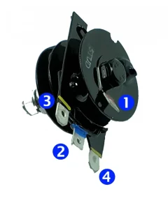
@Richard Tool here are the steps involved with testing your rectifier.


ORIGINAL RECTIFIER
Electricaly challenged

AFTERMARKET RECTIFIER
Electricaly challenged

AFTERMARKET REGULATOR/RECTIFIER (replaces zener and rectifier)
Electricaly challenged

You cannot test the new MOSFET regulator/rectifiers in this way, as they don't use standard diodes.
If you have a factory original rectifier, make sure you have a new battery in your multimeter - the diodes are chunkier than on the modern equivalents.


You should have 8 numbers - follow the process below, and write the numbers down as you go, so you don't lose track.

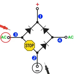
In the tests below - the STOP sign on tests 1, 2, 5 and 6 shows no voltage is flowing.

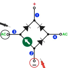
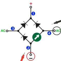
For the remaining tests 3, 4, 7 and 8 you should see a value on your multimeter. This will vary per unit but importantly the value from all four readings should be the same (within a few ohms)


TEST 1
Electricaly challenged

TEST 2
Electricaly challenged

TEST 3
Electricaly challenged

TEST 4
Electricaly challenged

TEST 5
Electricaly challenged

TEST 6
Electricaly challenged

TEST 7
Electricaly challenged

TEST 8
Electricaly challenged

If you are not seeing the desired values on just one of these tests, it means that you have a malfunctioning component (diode) within the rectifier.
Unfortunately, these are not user serviceable or repairable, so you need to replace it.
Make sure you throw the defective part away, rather than put it in a drawer in your workshop. This will make sure it doesn't find it's way back on to a bike in the future!!!


Hope this helps!
 
Thanks all for the help -
maylar - baseline is 1. - the number on display at start up for every function- don’t know why it isn’t zero but it indeed means no current.
gtiller- Thanks - VERY helpful - tests 1,2,5 & 6 show no current
Values for others are:
3 - .468
4 - .463
7 - .454
8 - .452
I will repeat test this evening with new batteries.
Thanks again- RT
 
In testing a suspect podtronics 200W with ohm setting @ 200 my numbers are as follows:
1. stop 2. 176.3 3. stop 4. 176.4 5. stop 6. 12.0 7. stop 8. 11.4
@gtiller I guess this is ready for the trash can. From your knowledge can you tell from these #s what it was doing? Sending A/C to battery, not charging at all? It will be replaced, just curious.
 
I would suspect it's just about working as you have all the stops in place and all the reverse flows are open with 2 lower resistance, however it's too risky to continue as those low resistance diodes are going to fail.
 
so I have bench tested original Zener diode by doing the following :

mounted diode on z plate - placed two new 6 v drycell batteries in series - voltage measured 13+ v.

connected dry cells in series with variable power supply which can produce 15 v so total capability 28 v ?

connected all to diode with ground to positive and placed 65w automotive headlamp bulb in circuit as resistor between negative side of diode and power.

lamp lit immediately upon connection without even turning on variable power supply .

took all apart and used variable power supply alone across diode and had current at very low voltage-

I take this to mean that diode is shorted and therefore no good - am I correct ?

Thanks all for any input and babysitting me electrically - RT

Be sure the polarity of your test is correct. Positive ground for that old zener. If reversed, it'll conduct at much lower voltage (under 1 volt usually).
 
Ran test again with variable power supply and multimeter- red leads connected to mounting stud of diode @ Z plate & black leads connected to spade terminal on diode . Both power supply & multimeter showing conduction @ .1 v - so is diode bad ?
 
Ran test again with variable power supply and multimeter- red leads connected to mounting stud of diode @ Z plate & black leads connected to spade terminal on diode . Both power supply & multimeter showing conduction @ .1 v - so is diode bad ?

Yep. Toast.
 
I’d fit the original equipment and test the Zener by revving up and seeing what the voltage reaches.
I’m a long way from running the engine - just read through threads on Podtronics/ alternator and even the original poster says there are many thousands of Podtronics in use and relatively few alternator failures - I have had a Podtronics in my ES2 for many years with no issues- sealed battery as well . 6V dynamo so perhaps that makes a difference vs alternator - once again I am handicapped by my lack of electrical knowledge.
 
I think the standard shunting type reg/rec units like the podtronics and used on nearly all modern bikes are fine with standard norton setup. Issues more likely as you make other changes like LEDs and LiPo batts. With LEDs etc you're lowering power loading and once batt is fully charged that excess alt output is shunted back to alt coils and makes heat. Like many things in life there needs to be a certain amount of balance to output vs consumption.
 
@Richard Tool the DC regulator for a 6 volt dynamo based charging system is a very different can of worms to an AC regulator/rectifier for a 12 volt alternator based charging system.

Your 6 volt unit is all about producing a stable supply rather than any conversion from AC.


I am just speculating here, but do bear in mind that Podtronics was bought by Coventry Spares, and manufacturing was outsourced to Taiwan a few years ago.

The product line was rationalised, and I would suggest they are not built with the same care and attention as they were when Bob Kizer was at the helm.

I do wonder if this is why Tri-Spark have seen issues with interference and I question whether it is a good thing that the single phase unit is now just a three phase with one of the yellow AC input wires cut off.
 
I think the standard shunting type reg/rec units like the podtronics and used on nearly all modern bikes are fine with standard norton setup. Issues more likely as you make other changes like LEDs and LiPo batts. With LEDs etc you're lowering power loading and once batt is fully charged that excess alt output is shunted back to alt coils and makes heat. Like many things in life there needs to be a certain amount of balance to output vs consumption.

So run incandescent bulbs with lights on all the time ( which one should do regardless) and standard battery and I will decrease the chances of a damaged alternator if I understand correctly, yes ?
 
Status
Not open for further replies.
Back
Top