Thanks for visiting Access Norton
- Guest view limit reached
- Create a free account (more details)
- Already a member? Click here to login
You are using an out of date browser. It may not display this or other websites correctly.
You should upgrade or use an alternative browser.
You should upgrade or use an alternative browser.
Electricaly challenged
- Thread starter Richard Tool
- Start date
- Status
- Not open for further replies.
- Joined
- Feb 10, 2009
- Messages
- 3,166
I’d be the last person to say Aprilia fools know more than old Nortonians, but...
https://www.apriliaforum.com/forums/showthread.php?240785-Facts-about-shunt-based-regulators
https://www.apriliaforum.com/forums/showthread.php?240785-Facts-about-shunt-based-regulators
The Aprilia guys don’t know more - it’s exactly the same discussion as we have on here time and time again.
They also have the same characters as we do - nay sayers constantly stirring it up at every opportunity and telling everyone to buy a ten bucks unit from eBay because they are all the same, and it doesn’t matter and they’ve got clever people (like our very own @Jeandr ) who present facts, charts, plots, research which then gets washed over and overlooked.
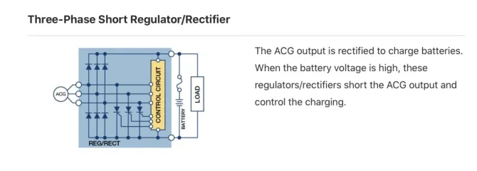
It is well documented how a short-type reg/rec works however, it is not documented on the websites and instructions of the companies that make and sell them.
If people are made aware of the method of operation, and are still happy to go ahead with using them, then great!
But it’s my experience that most people don’t understand. A motorcyclist typically is not an electrical engineer, and they just want to get on the road and ride. Preferably not having to push the bike home again because it’s conked out, and defiantly not wanting to rebuild a grenaded primary side.
A zener that is shunting over current to earth is not the same as a reg/rec shorting out the AC input wires.
An alternator running with it’s coils shorted out cannot be defined as running at full load.
Bonfide power consumers like light bulbs and coils that take the power and doing something with it are a true load.
Crossed wires that make the alternator coils get hotter and hotter inside the potted (resin encapsulated) stator is not healthy, and is I believe the reason why we are seeing more failures nowadays.
Throw in to the mix that we are adding more powerful alternators and are reducing load by swapping to LED lighting means that problem will continue to become more and more prevalent (but I’ve bleated on about that enough in another post)
- Joined
- Feb 10, 2009
- Messages
- 3,166
Gtiller you’ve seen more in the AccessNorton discussions than I’ve managed to.
I think the Aprilia forum thread is worth reading with an open mind.
I think the Aprilia forum thread is worth reading with an open mind.
Tornado
VIP MEMBER
- Joined
- Dec 5, 2017
- Messages
- 5,257
With the Zener, the shunted current has to go through the voltage drops across the rectifier, the the Zener and the alternator coils.
At each component, power in the form of heat, equivalent to the component’s voltage drop x the current has to be dissipated.
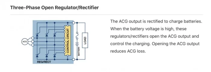
It makes sense that a reg that shunts the AC could have less heat to get rid of than one that includes the rectifying diodes in the shunt circuit. But it depends on exactly what components are in that there black box.
This guy did some tests.
Thanks for this document. It specifically addresses alt coil temp while shorted for 40 minutes at 3k rpm. Showing it tops out at 80 deg C notevenenough to boil water and significantly lower than heat transferred from engine casing I'd bet.
This puts this issue to bed IMHO.
Not losing anymore sleep with this "issue".
- Joined
- Feb 10, 2009
- Messages
- 3,166
Thanks for this document. It specifically addresses alt coil temp while shorted for 40 minutes at 3k rpm. Showing it tops out at 80 deg C notevenenough to boil water and significantly lower than heat transferred from engine casing I'd bet.
This puts this issue to bed IMHO.
Not losing anymore sleep with this "issue".
I’d like to have seen the temperature results for open circuit and with a load in series too. Might have been higher than when short-circuited.
- Joined
- Jan 2, 2013
- Messages
- 4,255
My study of electricity and magnetism is now about 55 years old, so I am not going to claim I fully understand the pros and cons of shorting the alternator coils. Therefore take the following with some caution.
I think shorting the coils does more than simply directing current to ground (earth), with a commensurate heat gain. There is also the effect on the magnetic flux within the stator. Stators are made with laminated iron cores for a reason that I do not remember, but one can expect the iron core improves the generation of current, otherwise it would not be there.
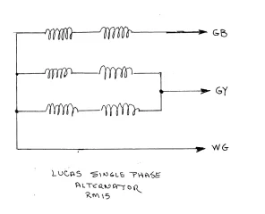
Now consider the older three wire stators: the sketch below shows how these were internally wired.

Before the days of Zener diodes and electronic regulators, the main lighting switch controlled the alternator's output to match the load.
In the OFF position, the lighting switch connected GY to WG, i.e. shorting the parallel pair of coils. The battery was being supplied by the GB series pair, and the current delivery to the load was MINIMAL in this configuration.
In the PILOT position, the lighting switch open circuited GY, and the current output of the alternator was increased.
Here is the crux of the issue: the same series pair of coils, connected to the GB wire, increased the current output, when the shorted coils were open circuited. This indicates shorting the coils affected the magnetic flux in some way, which IIRC from Physics 101, affected the flux in the iron core.
In the HEAD position, the lighting switch connected GY to GB, giving full alternator output.
The function of the lighting switch can be verified by studying the switch positions in the wiring diagram given for the 650 American (the 7th down from the top): https://www.accessnorton.com/NortonCommando/early-norton-wiring-diagrams.20232/
The bottom line: shorting the coils affects the magnetic flux and decreases the stator output. Now (take this with caution), might not shorting the coils in a 2 wire stator, similarly affect the magnetic flux and decrease the induced current in the coils as well, thereby not creating the heat load one expects? Wish I could positively answer that, but I think it is worth considering.
Slick
I think shorting the coils does more than simply directing current to ground (earth), with a commensurate heat gain. There is also the effect on the magnetic flux within the stator. Stators are made with laminated iron cores for a reason that I do not remember, but one can expect the iron core improves the generation of current, otherwise it would not be there.
Now consider the older three wire stators: the sketch below shows how these were internally wired.

Before the days of Zener diodes and electronic regulators, the main lighting switch controlled the alternator's output to match the load.
In the OFF position, the lighting switch connected GY to WG, i.e. shorting the parallel pair of coils. The battery was being supplied by the GB series pair, and the current delivery to the load was MINIMAL in this configuration.
In the PILOT position, the lighting switch open circuited GY, and the current output of the alternator was increased.
Here is the crux of the issue: the same series pair of coils, connected to the GB wire, increased the current output, when the shorted coils were open circuited. This indicates shorting the coils affected the magnetic flux in some way, which IIRC from Physics 101, affected the flux in the iron core.
In the HEAD position, the lighting switch connected GY to GB, giving full alternator output.
The function of the lighting switch can be verified by studying the switch positions in the wiring diagram given for the 650 American (the 7th down from the top): https://www.accessnorton.com/NortonCommando/early-norton-wiring-diagrams.20232/
The bottom line: shorting the coils affects the magnetic flux and decreases the stator output. Now (take this with caution), might not shorting the coils in a 2 wire stator, similarly affect the magnetic flux and decrease the induced current in the coils as well, thereby not creating the heat load one expects? Wish I could positively answer that, but I think it is worth considering.
Slick
- Joined
- Feb 10, 2009
- Messages
- 3,166
Like everyone who rode an old bike, I did thousands of miles with four out of six coils shorted via the light switch. Enfield were pulling the same trick in 1988, at 12 volts.
Who knows whether the open coil stators should have burnt out? They were shaken to bits first.
Who knows whether the open coil stators should have burnt out? They were shaken to bits first.
- Joined
- Dec 8, 2018
- Messages
- 61
@Richard Tool here are the steps involved with testing your rectifier.
ORIGINAL RECTIFIER
View attachment 13178
AFTERMARKET RECTIFIER
View attachment 13179
AFTERMARKET REGULATOR/RECTIFIER (replaces zener and rectifier)
View attachment 13180
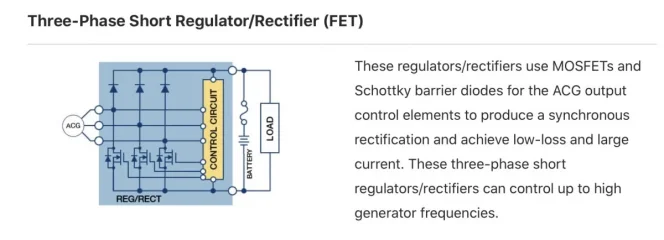
You cannot test the new MOSFET regulator/rectifiers in this way, as they don't use standard diodes.
If you have a factory original rectifier, make sure you have a new battery in your multimeter - the diodes are chunkier than on the modern equivalents.
You should have 8 numbers - follow the process below, and write the numbers down as you go, so you don't lose track.
In the tests below - the STOP sign on tests 1, 2, 5 and 6 shows no voltage is flowing.
For the remaining tests 3, 4, 7 and 8 you should see a value on your multimeter. This will vary per unit but importantly the value from all four readings should be the same (within a few ohms)
TEST 1
View attachment 13181
TEST 2
View attachment 13182
TEST 3
View attachment 13183
TEST 4
View attachment 13184
TEST 5
View attachment 13185
TEST 6
View attachment 13186
TEST 7
View attachment 13187
TEST 8
View attachment 13188
If you are not seeing the desired values on just one of these tests, it means that you have a malfunctioning component (diode) within the rectifier.
Unfortunately, these are not user serviceable or repairable, so you need to replace it.
Make sure you throw the defective part away, rather than put it in a drawer in your workshop. This will make sure it doesn't find it's way back on to a bike in the future!!!
Hope this helps!
I have been trying to test the original rectifier on my 1975 Commando Mark III 850 electiric, but when reading your post (this one) I realize I might not be doing it correctly. Here's the link to my post on a thread I created asking for help with my charging system: https://www.accessnorton.com/Norton...bleshooting-question.30024/page-2#post-466569 (Note: there is an error in the photo. The test shown on the right side should read "Battery (-) connected to rectifier terminal..., not Battery (+) connected to rectifier terminal...".)
I did the test thinking that the mounting bolt to the frame bracket didn't come into play as one of the relevant terminals in the operation of the rectifier; I just thought it was for mounting only. I drew that conclusion because I got no current flow from/to the bolt to any of the three terminals. That is why I said:
"I get no light with either the (+) or (-) battery terminal connected to the mounting bolt and the bulb connected to any of the rectifier terminals."
The photos in your post show that four, not three, connection points are used in a rectifier test. The top photo is the most similar to my stock rectifier in that it shows a mounting bolt with a tab for wire connection and three terminals. Does all this mean that the mounting bolt on my rectifier is a fourth terminal and is the same as number 1 in your top photo? If so, I will test the eight possibilities as shown in the diagrams to see if my rectifier is good or bad.
- Joined
- Nov 20, 2004
- Messages
- 21,090
I did the test thinking that the mounting bolt to the frame bracket didn't come into play as one of the relevant terminals in the operation of the rectifier; I just thought it was for mounting only. I drew that conclusion because I got no current flow from/to the bolt to any of the three terminals. That is why I said:
"I get no light with either the (+) or (-) battery terminal connected to the mounting bolt and the bulb connected to any of the rectifier terminals."
The photos in your post show that four, not three, connection points are used in a rectifier test. The top photo is the most similar to my stock rectifier in that it shows a mounting bolt with a tab for wire connection and three terminals. Does all this mean that the mounting bolt on my rectifier is a fourth terminal and is the same as number 1 in your top photo? If so, I will test the eight possibilities as shown in the diagrams to see if my rectifier is good or bad.
That's a different (4-diode) rectifier.
Mk3 and the one in your photos is a 2-diode 2DV 406 which has no 'ground' stud.
Edit: If your rectifier has "a mounting bolt with a tab" then it's not the standard Mk3 rectifier.
Last edited:
- Joined
- May 28, 2003
- Messages
- 2,591
A zener that is shunting over current to earth is not the same as a reg/rec shorting out the AC input wires.
It would seem to me the zener only PARTIALLY shorts SOME current of the over voltage being supplied...not all...never all but this small amount is ALWAYS shunting ...some... once the battery and supply is up to 14.3.
The shorting type regulator...yes... will short out the coil wires. The main difference is they only short out for a PORTION of the waveshape cycle.
For general discussion...the zener shunts 15% current to ground ALL(100%) of THE TIME
and the shorting regulator shorts out 100% of the current during the last 15% of the time/cycle.
They are for the most part doing the same job but in a different way.
- Joined
- Nov 20, 2004
- Messages
- 21,090
(Note: there is an error in the photo. The test shown on the right side should read "Battery (-) connected to rectifier terminal..., not Battery (+) connected to rectifier terminal...".)
LH. "Battery (+) connected to rectifier terminal 2.
Light connected to 1 & 3 = 1 & 3 light."
Yes.
RH. "Battery (-) connected to rectifier terminal 2.
Light connected to 1 & 3 = 1 & 3 light."
No. Bulb should not light but I'm guessing "1 & 3 light" is another error as it's unlikely both diodes would have failed...but?
- Status
- Not open for further replies.
Similar threads
- Replies
- 10
- Views
- 515
- Replies
- 5
- Views
- 675


