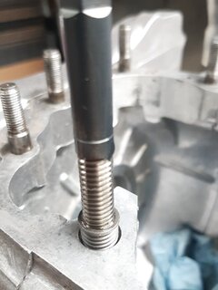
I noticed your head has been decked
So the story of this head:
It's the summer of 1978. I have ridden from south eastern New York State westward through the midwest to South Dakota then angled northwest to Montana, up into Alberta, west through Banff, south through the Okanagan Valley and Washington State, westward along the Columbia River to Portland OR at the Pacific coast then south on the coast highway to southern California.
There some forgotten reason had me remove the head and barrel. I took the head to Jack Hateley I think in Burbank for refresh. Their shop was very backed up and they offered to swap heads with me instead of having me wait for mine. I should have waited.
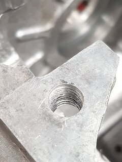
My head was the original Combat head with the C stamped on top. The head they offered was not a Combat head but they said they had somewhat made it into one. Perhaps they decked it, I don't know. They did show me that when they were porting out the intakes they once broke through to the outside. They showed me the spot and how they had welded it up. They had a good reputation, I think I have read Jack had ridden for Norton ?? So I figured they knew what they were doing. I swapped my head for theirs. Bad move.
On my return trip to New York somewhere eastbound on an interstate in Iowa while decelerating into a rest area the weld let go.
The small weld material went into the chamber and bounced around in there taking out the spark plug. I remember pulling that plug and seeing the ground electrode bent and porcelain mosty gone and wondering wtf happened here?!? In due course I found the open hole where the weld had been. Well crap, what do I do now. I had some blue silicone sealer with me so I squirt that into the finned area of the opening and let that sit overnight while I get some sleep on a picnic bench or wherever. That's how I travelled then, sleeping under bridges and such.
Come morning the silicone has set up enough and I set off for New York. The bike took a beating on that trip and the following spring I bought a used Honda CB750 and used that for several years before retiring from motorcycling.
The Norton was dismantled at some point after that ill fated trip and only now is being slowly addressed and ready for reassembly.
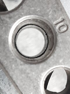
This shot of the piston tops reveals some of the carnage that happened in one chamber.
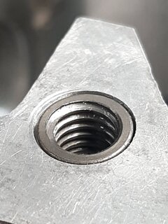
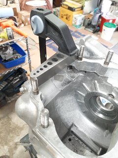
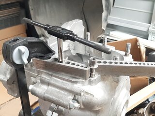
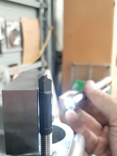
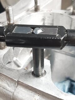
So I don't really have much history of the head beyond that. It makes sense what you say about perhaps the head is thermally distorted, the center having risen thus tilting the studs inward. Though I cannot remember specifics I am fairly certain I had no torque wrench and very likely had uneven clamping across the head that perhaps added to the distortion??
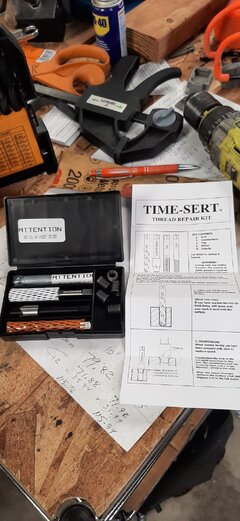
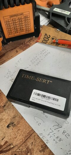
@marshg246 is going to put a replacement Combat head together for me so all this is not an issue but an opportunity for me to experiment and learn and play with new toys (1,2,3 blocks, machinist squares, micrometers etc.)


")