Stator to rotor clearance

Status
Not open for further replies.
Joined
Dec 28, 2008
Messages
2,035
Country flag
I have read just about all the posts dealing with getting a uniform clearance between stator and rotor. The 2 most common seem to be 1) machine the rotor. 2) exploit the wiggle room, if available, between the engine and inner primary. 3) enlarge the holes of the stator that the stand-off studs fit through. 4) somewhere in this forum someone suggested smacking the stator with the goal of bending the stand-offs. ( I read that post with a cringe)

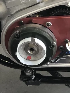
The clearance on the Norton I am assembling has about .012 to .013 clearance between the 6 and 12 O'clock position, but tightens up gradually to unacceptable at the 3 O'clock position; just where you want the most clearance. I have rotated the stator using all positions and get the same issue. While mounting the inner primary, knowing the issues associated with stator/rotor, I use what little wiggle room I had to move the inner case as far rearward could. (yes center fixing stud was measured and shimmed properly)

The stator and rotor are both Wassell branded. I have several rotors including OE Lucas, I measured the spares (junk?) against the new Wassell and see variation in the low tenths; insignificant.

I have yet to remove the stand-offs and check them for signs of being bent; I have plenty of others I can try.

My question: If the stand-offs check out I'm thinking that opening the inner part of the stator with an abrasive wheel (Dremel type, but turned by cordless drill). I fear that I may ruin the stator. Has anyone tried something like this?

Best.
 
I usually just use some 10 thou brass shim stock (non magnetic) between the rotor and stator at 120 degree intervals. Tighten the stator nuts up, remove the shim stock and.. Bob's yer uncle, Bernards yer aunt!
 
Tweak the studs a bit with the box end of a wrench and the stator off to move the alignment a tad in the desired direction. Then use a cut down plastic coke bottle as a shim to center the stator about the rotor before tightening the nuts down.
 
I ended up machining a mandrel to take the new 'Lucas rotor (which had iirc around an even 0.009" clearance to the new 'Lucas stator) and reduced the OD but forget by how much to increase that clearance. It might have been 0.015" +
I had already opened the three mounting holes in the stator to around 8.3 mm so it was easy to centre over the rotor and used new cupped washers for the three nuts so any force did not skew the stator on the mounting studs which seemed to work.

I would be hesitant to alter the bore of the stator personally.

Stator to rotor clearance
 
I would try opening up the 3 stator mounting holes slightly. You only need to move it a few thou to get the correct clearance. That would be the simplest and safest way to do it.
I know you said inner primary was aligned correctly but I put a spacer on the central stud and tighten the outer cover mounting nut on to it to simulate the situation when everything is assembled when checking clearance.
 
  • Like
Reactions: baz
Sometimes a few strokes with a round file in the stator mount holes in the direction you need to go is enough
Or just open two of the holes a little
After fully tightening I always turn the motor to every position on the clock to check for a minimum of 8thou
Sorry if I'm teaching how to suck eggs but there could be some younger viewers
Hopefully!
 
Non-magnetic spacers for me too. I use thin fibreglass sheet (G10) in 3 positions.
The stator gets pulled out of kilter by the rotor magnetism.
Funny how I never have this problem on Triumphs, but Commandos do seem to be a pain to set up correctly
 
the problem is the commando has the primary case bolted to the crank case , any discrepancy in the machining of the mating faces / mounting holes
will reduce the air gap as Road scholar quoted i had to move the primary case as far rearward as i could so that means the casing is movable by a small amount
which will alter the air gap

On triumph unit twin motors the inner primary is cast as one piece with the D/S case so less room for error bent mounting studs are often the cause of premature failure on triumph twins
 
I don’t like the idea of bending the studs personally.

I’ve taken to having the rotors turned down to ensure a .020” gap (so .040” under size). I then use a strip of plastic milk bottle when tightening. I still sometimes find it necessary to enlarge the mounting holes as well, sometimes they are just too tight and / or the 3 holes not quite aligned.

Stator to rotor clearance
 
I don’t like the idea of bending the studs personally.

I’ve taken to having the rotors turned down to ensure a .020” gap (so .040” under size). I then use a strip of plastic milk bottle when tightening. I still sometimes find it necessary to enlarge the mounting holes as well, sometimes they are just too tight and / or the 3 holes not quite aligned.

View attachment 83056
When you take .020" off do you notice any drop in the charge rate?
 
When you take .020" off do you notice any drop in the charge rate?
No, but, I haven’t measured it properly either !

The reason I do this though is that even with something over .010” I still had some hard rubbing going on. I can only think this is due to crank flex at higher rpm, some have argued against this, but I just can’t think what else it could be ?
 
No, but, I haven’t measured it properly either !

The reason I do this though is that even with something over .010” I still had some hard rubbing going on. I can only think this is due to crank flex at higher rpm, some have argued against this, but I just can’t think what else it could be ?
Well the only other thing it could be is a worn out main bearing,a loose main bearing or a loose rotor?
All of these would be self evident so I think you are right
I'm often above 6000 rpm and very occasionally 7000rpm on my 750 and I've never touched anything with a 3 phase Lucas stator and Lucas rotor
Now have an Alton setup and still not a problem so far fingers crossed
 
Might make sense to check the mating surfaces between the crankcase and the inner primary are square and sitting true??
 
  • Like
Reactions: baz
Cut up 4 pint plastic milk container shimming for me .... semi skimmed obviously :):)
 
In Norman White's Norton Commando Restoration Manual, he mentions reducing the diameter of the three mounting studs in the region of the stator, then using playing cards as shims to center it on the rotor.
 
Or as previously mentioned open the holes in the stator slightly, i have to say my view wouldn't be to reduce the mounting stud diameter as there only 5/16 mild steel
 
I can't help but wonder .... what Norton did in the 10 years from when they built my bike (1962) to the Commando years?

I have pulled my inner primary cover several times, each time of course requiring stator and rotor removal. Each time I put things back, I obtained the optimum 0.005 clearance all way round. Is it just an Atlas / Dommie thing, or did they let quality control get out of control?

Slick
 
Personally I’m not sure it is a Norton issue at all. It happens on other bikes too. The common denominator being the use of new parts, ie rotors and stators made in the far East.
 
Status
Not open for further replies.
Back
Top