Rewiring with Mo.Unit Blue

ntst8

VIP MEMBER
Joined
Feb 14, 2004
Messages
1,757
Country flag
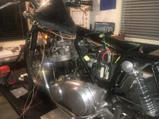
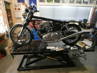
I have been having fun with the wiring on my bike on and off for a few years. Finally come to the conclusion recently that pulling out the old loom and doing a bespoke version would be both therapeutic and big step ahead. So Christmas Eve out came the old loom.
Rewiring with Mo.Unit Blue

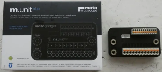
I happened to look in the Motogadget website at around the same time, after reading some threads on here, and found that they had come out with a new fuse/control box during 2017. Very neat it is and a step ahead of their old unit, setup etc can be via Bluetooth to a smartphone app for instance. I have never been good with temptation so one of these is now about to go in.
Rewiring with Mo.Unit Blue
All handlebar switches are used for earth loop signal continuity only, 12V only goes from the power side of the unit to where it is needed. The unit acts as a relay, flasher relay, etc. It can also do tricks like auto turn the lights on once the engine is running, timed auto stop on the indicators, modulate the brake light etc.

The target is to be up and running again for our annual club rally in March, time will tell.

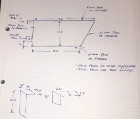
At present – after much head scratching and then a cardboard mock up I have a support bracket being made to mount the M.Unit and the Alton starter relay.

About to happen – the M.Unit can only run negative earth so the Alton starter needs to be converted. Paul at Alton has been very helpful with an instruction leaflet and general feedback, some dismantling and minor internal alteration is needed but it doesn’t look too daunting.

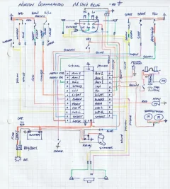
I have drawn up a wiring diagram, the attached won’t be the final version but is getting close.
Rewiring with Mo.Unit Blue

One thing I have just noticed in the book is that a sidestand switch must be used and linked to the sidestand cutout input. You can chose between Normally Open and Normally Closed for the switch so NC setting and input wired to earth should do the trick.

My workshop pace is usually slow but will update when there is some progress.
 
Looking good. Please keep posting your progress. I'm close to starting a similar task on my restomod MK3, and I'll look at your circuit drawing for ideas.

Ken
 
Will do on the final diagram Slick, although my "CAD" system is a fountain pen and a box of coloured pencils!
A note that the wiring colours are non Norton, i bought the optional wiring kit that Motogadget offer and the handelbar switch gear is from CNW so those are the colours in the diagram above. I plan to laminate a copy for the toolkit once it is finalised.
 
Nice.

I have a sidestand cutout switch on the Duc and I hate it. Safe but PITA. Could possibly run a dummy loop to fool the switch that it is always up?
 
One small step - the indicator idiot light needs to be fed via two diodes, so after a session practising soldering wires together....
For reasons unexplained the live feed wire on the idiot light had two deep cuts, not previously noticed, through the insulation and partly through the wire! That was trimmed just short of the damage and the diodes soldered direct to it. 1 N4001 diodes called for but had to go with 1 N4004's, cost almost nothing for a pack of 4 from an electronics stop.
Rewiring with Mo.Unit Blue
The finished article below, showing mistake No 1 - should be one white wire and one yellow, oh well never mind. Colour's will be correct from the yet to be fitted connectors.
Rewiring with Mo.Unit Blue
The good news is that the idiot light performs correctly under power, shines brightly on negative earth connection, no light on reversing the hook up.

Ken - i enjoy your build threads, will be good to see what you come up with.
David - agreed, the NC menu option with signal wire to earth will read as stand being up.
 
Some progress;
Wiring diagram - only one change. I have an IronJohns oil tap with electrical cut out switch. Previously this was in line on the power supply to the electronic ignition, as it was with the original wiring. It would be smarter to wire it as the sidestand switch, so again switching on the signal side, uninterrupted supply on the power side for little to zero voltage loss.
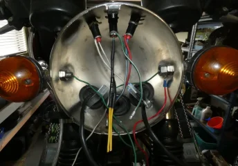
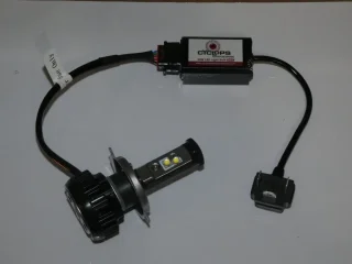
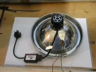
To take advantage of the auto on lighting option, and possibly the use of indicators as running lights, a selection of LED lights are on their way to keep the power draw to a manageable level at around town speeds. Yet to arrive (should be this week) LED indicator bulbs and tail/brake light board from Paul Goff. Just arrived a Cyclops LED headlight bulb from Adventure Bike Australia. The latter being a simple fit since a Halogen bulb was already in use.
Rewiring with Mo.Unit BlueRewiring with Mo.Unit Blue
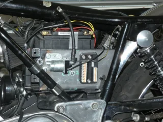
Also just arrived the mounting plate for the M.Unit and the Alton starter relay. It also has 2 angle brackets as locaters for the battery behind, Odyssey at present. The sidecover has had the tool box removed and the mounting plate will be attached to the frame via 4 grab rail P clamps (all sitting loosely in place in the photo). Battery removal will be a bit of a bind but hopefully that will be infrequent.
Rewiring with Mo.Unit Blue Rewiring with Mo.Unit Blue
The plan from here is, once the Paul Goff bits and pieces arrive, complete the wiring then remove and send the mounting plate off for powder coating while the polarity change on the Alton starter is worked through.
 
Last edited:
Don’t know if you know, but Mr Goff also does a very neat drop in LED bulb. He shows it on his web site as being no deeper than a stock bulb with holder (his has the connector on a short piece of wire).

He also does a slightly shallower lens unit to leave more ventilation space in the shell, not compulsory, but a nice to have.

I got his LED headlight bulb, shallow lens and super bright LED pilot bulbs and will be fitting to the Commando and Bonnie at the weekend. I’m due some shed time...!


Rewiring with Mo.Unit Blue
 
Last edited:
Thanks, i ordered the Cyclops first and then found the one on Pauls site once it was too late.
His is quite reasonably priced too.
Will be interested to see how yours works once fitted.
 
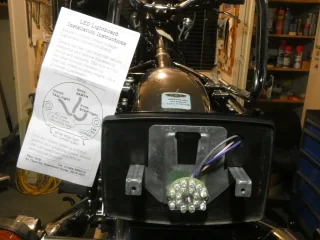
The last of the bits fitted, the instructions are brief and make perfect sense ... by the time you have finished fitting the board.
Quite compact but seems to be quite bright when hot wired to a battery.
Just need a spare day to wire it all up now.
Rewiring with Mo.Unit Blue
 
Decided to do the polarity change on the Alton before the wiring, there was public holiday here last week so spent the afternoon in a friends workshop - moral and technical support. Alton recommend that the starter is returned to them for the mod but NZ to France wasn't going to happen, and the instructions they provided are very clear.
Rewiring with Mo.Unit Blue
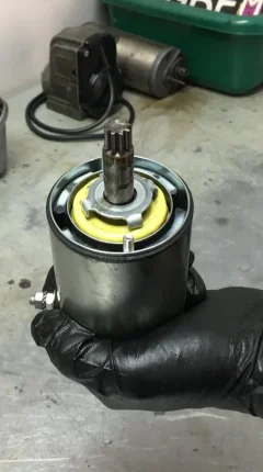
Starter removed (pic above), the brush end came off next, new locating notch to be cut 90 degrees clockwise from the current one, two new through bolt holes to be drilled and all back together. We used a piece of string to measure the circumference, marked and folded that in 4 to get the 1/4 circle and marked the new notch location. Small hacksaw and small file to tidy up.
We hot wired the starter to the battery to test and all spins correctly on negative earth, and without any strange noises. Beer served at that point.
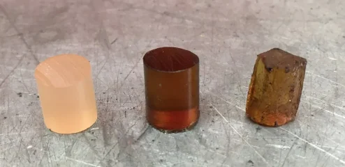
Alton also provided replacement bungs for the starter, some at the age of my starter have needed to be replaced so they were sent out free of charge just in case - my thanks to Alton. We did that while all was apart. Turns out mine were in good condition, so have kept the old ones as spares.
Pic shows new (left), my used (middle) and a used one from another bike (right) which had proved soft and been replaced recently.
Rewiring with Mo.Unit Blue
Primary chain adjusted while we were in there and all is buttoned up again.
 
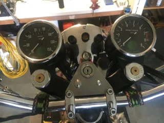
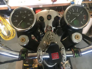
There is always one more thing - mount for the ignition switch modified.
On left - a motogadget momentary switch, will be the hazard light on/off. Needed to be very shallow to fit over the top yoke.
On right - a power outlet, scavenged off my Yamaha so the mounting is a bit of a bodge, too deep to fit over the yoke.
Rewiring with Mo.Unit Blue Rewiring with Mo.Unit Blue
Need to find a rubber bung to go in the old light switch hole on the headlamp shell.
 
Getting close-ish, all wired up and the engine started first pop, lights work, horn works, setup with the M Ride app works well.
Bluetooth proximity for keyless start works.
Aren't there always a couple of things to sort though, not finishing the loom tape until all gremlins are banished.
Having some fun with the hazard/indicator functions and for some reason the kill switch is working in reverse - haven't found an option to swap NO vs NC for that one.
 
Thanks CJ.
Haven't had much shed time of late so trouble shooting has largely been on hold, and with some distractions here will be for a week or so yet.
Motogadget have advised that there is no option for reversing kill switch action, i can't imagine that swapping the leads will have any effect so working in reverse may make a nice security feature.
RGM Solid State Battery status monitor - the original installation instructions apply to +ve earth only, for negative earth installation red is still +ve, black is still -ve and only the polarity on the idiot light wires changes. I had mistakenly swapped the feed wires over as well.
 
NIICE JOB! Just what I am considering doing to my old girl as next step to keep her running reliably.
Wondering if you considered other centralized wiring options from Ultima or Fuseblocks before going with the M.Unit?
I do worry a bit about long term electronic durability of the M.Unit. Complexity has its downside.
 
I agree on the durability question, time will tell.
I had looked at Centech Wiring, Eastern Beaver and Fuzeblock. I actually have an Eastern Beaver PC-8 on the shelf, that will now likely go in my ES2 at some point.
Life has been a bit of a mess here lately so i haven't been back in the shed in over a month, hopefully i will be onto it in the next few weeks.
 
Thanks CJ.
Haven't had much shed time of late so trouble shooting has largely been on hold, and with some distractions here will be for a week or so yet.
Motogadget have advised that there is no option for reversing kill switch action, i can't imagine that swapping the leads will have any effect so working in reverse may make a nice security feature.
RGM Solid State Battery status monitor - the original installation instructions apply to +ve earth only, for negative earth installation red is still +ve, black is still -ve and only the polarity on the idiot light wires changes. I had mistakenly swapped the feed wires over as well.


Iain - this is what I did:

A while ago I was searching for a nice kill switch and came across this billet Zeta, which the manufacturer told me was a Normally Closed switch. I had to fettle it a bit and have the mounting holes widened by a mm or so, but it was way better than the cheap n cheerful plastic ones I could find, so I went for it.

Rewiring with Mo.Unit Blue


Turns out, as I was wiring stuff up recently, it is a NO switch, not a NC switch. Bummer.

Also turns out I have a SPDT NC or NO horn relay switch and I found a suggestion on the Triumph Rat board that led me to the following solution that I wanted to float:

The relay should be wired with power to the coil from the ignition switch. Wire the TriSpark power feed from the Ign Switch, through the NC contacts on the relay, and then to the TS.

1. Connect the Tri-Spark black/yellow wire to 30 and 87a to ignition coil

The ground connection to the relay coil should be wired thru the kill button, thus completing the circuit.

2. Connect 12v- to 85
3. Connect Kill switch to Earth and 86

When you press the kill button with the ignition on, it should energize the coil in the relay, which will in turn open the normally closed contacts 30 & 87a and remove power from the TriSpark.
 
Back
Top