Hello everyone!
I have a 1973 Norton Commando 850 that has a problem with getting spark on the left side. I cannot get ANY spark to come from that side.
Here is what I know:
Both coils are good (if I swap the wires from the right side coil to the left, the left fires, so it has to do with the wires coming to the coils)
Both plugs and plug leads are good (both work when I plug them in the right side)
Took the condensers off of my buddies running Norton to quick check if that made a difference, no difference, still no spark left side.
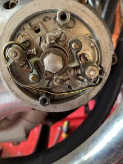
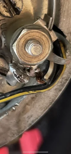
Checked the most right points (facing the bike on the right side, the lower right points connected to the black wire). There was some slight pitting but I cleaned them with 1000 grit and wiped and blew them clean, re-installed, still no spark.
I have a hunch that it has something to do with the points, but I am not completely sure.
What should I do? How do I test points, or how do I test the wires going to them?
I am VERY amateur with electrical related things, so if you recommend using a multimeter for any of your testing suggestions, please be as descriptive as possible for my sanity : ).
Next, my thought was swapping the points wires and if I get spark suddenly on the left and not right, then I would know it was problems with those wires or points.
Thank you so much for your time!
I have a 1973 Norton Commando 850 that has a problem with getting spark on the left side. I cannot get ANY spark to come from that side.
Here is what I know:
Both coils are good (if I swap the wires from the right side coil to the left, the left fires, so it has to do with the wires coming to the coils)
Both plugs and plug leads are good (both work when I plug them in the right side)
Took the condensers off of my buddies running Norton to quick check if that made a difference, no difference, still no spark left side.
Checked the most right points (facing the bike on the right side, the lower right points connected to the black wire). There was some slight pitting but I cleaned them with 1000 grit and wiped and blew them clean, re-installed, still no spark.
I have a hunch that it has something to do with the points, but I am not completely sure.
What should I do? How do I test points, or how do I test the wires going to them?
I am VERY amateur with electrical related things, so if you recommend using a multimeter for any of your testing suggestions, please be as descriptive as possible for my sanity : ).
Next, my thought was swapping the points wires and if I get spark suddenly on the left and not right, then I would know it was problems with those wires or points.
Thank you so much for your time!