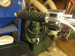
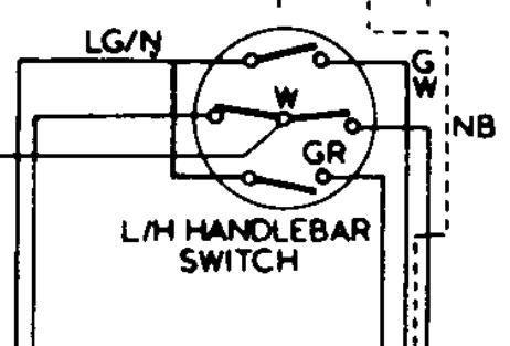
Lucas 169a controls

Eric1109

VIP MEMBER
Joined
Sep 16, 2024
Messages
34
Country flag
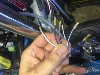
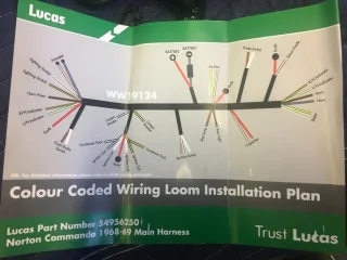
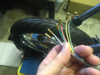
I purchased the reproduction hand controls 1971 to 1975. They have not come with description of color codes .. a few are same as Lucas harness turn signals. But lots of Colors I have no idea where they go. I’m using Lucas harness 54956250. It’s single harness no separate headlight harness. Can anyone steer me to where I can get wire color descriptions
Lucas 169a controlsLucas 169a controls
 
Left-hand picture:
Green/white to harness green/white.
Green/red to green/red.
Light green/brown to (the feed from the flasher relay) a wire your harness doesn't seem to have.
White to white however as there's no connection for the white/yellow (kill button to the ignition) then it serves no purpose unless white/yellow is wired to operate the ignition.
White/red isn't normally used unless you were to fit an electric starter. Also powered from white therefore although unused it is a live wire when the button is pressed if white is connected so insulate the bullet connector.

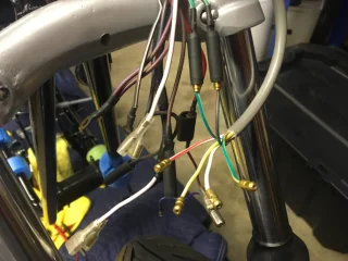
Right-hand picture:
Blue/white to blue/white (headlamp main/Hi beam).
Blue/red to blue/red (dip/Lo beam)
Blue to the headlamp lighting switch (terminal 8?).
White to white.
Purple/black (horn) can't be used without rewiring the horn as it's a feed, not a ground switch/wire.

Note that this won't just be a matter of plugging in some of the bullet connectors.
Regarding horn. Not what sure you mean by not a ground switch. Harness has 2 wires in harness at rear and one in headlight bucket. What do I need to do. I’m using an aftermarket two post horn. I have an original but needs quite bit of restoring and quite frankly it’s not really loud. Lucas 169a controls
 
Regarding horn. Not what sure you mean by not a ground switch. Harness has 2 wires in harness at rear and one in headlight bucket. What do I need to do.

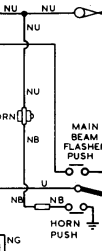
In the original system, power from the battery goes to the horn first (brown/blue, NU) and then to the switch which grounds to complete the circuit when the button is pressed.
Lucas 169a controls

In the later system the power goes to the switch first and then the horn so one side (terminal) of the horn connects to ground.
So would I not just connect both harness wires at backend to horn and single front wire to switch
 
So would I not just connect both harness wires at backend to horn and single front wire to switch

No, you need to connect one wire between purple/black and one horn terminal (you could possibly use the horn NB wire) and connect the other horn terminal to ground.
 
Really confused. Thought I would tackle turn signals first. I connected red
/green and white/green from harness to respective Colors in controls. Then did continuity tests by engaging control paddle up or down. three of remaining wires showed continuity (white green/yellow and yellow/white) Lucas 169a controlsLucas 169a controlsExample paddle up put tester on red/green all three of noted wires were positive for continuity. When paddle in center no continuity. When I tested paddle down white/green. The same three wires were positive. When paddles in center none of those three wires are showing continuity.
 
There shouldn't actually be a green/yellow wire unless they are using that colour instead of light green/brown.
I would expect continuity between that wire and the green/white or green/red (depending on the switch position either up or down but not central) but not the white or white/yellow.
 
There shouldn't actually be a green/yellow wire unless they are using that colour instead of light green/brown.
I would expect continuity between that wire and the green/white or green/red (depending on the switch position either up or down but not central) but not the white or white/yellow.
I just checked those three wires against each other and all three show continuity against each other regardless of paddle position. No power sources attached. Yes green yellow shows continuity with lever up down. Also in mix is that red /white has continuity with the three wires in question when bottom button depressed.
This is really kicking my butt.
There has to be easier way to wire a bike. Thought would be fairly easy. In past I have used a motogadget m unit. So easy. But they don’t work with positive ground.
 
I don't understand that as the white, white/yellow and white/red wires should be separate from light green/brown (green/yellow), green/white and green/red direction indicator wires which get their power from light green/brown (green/yellow) not white.
Lucas 169a controls
 
I don't understand that as the white, white/yellow and white/red wires should be separate from light green/brown (green/yellow), green/white and green/red direction indicator wires which get their power from light green/brown (green/yellow) not white.
Lucas 169a controls
I guess I could put a battery in and see where power goes. And maybe figure out which wires go together. Short of that il have to find someone local to come give me a hand.
 
Eric,

You seem to understand how wiring works.Put the battery in learn how the handlebar switches work. You don’t need to get help,just keep at it.
Mike
 
Hi guys,
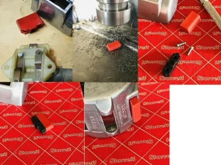
Do you have a source for the red kill button fitted to the late 169SA RH switch cluster? I could paint a black one of course, but would prefer a genuine red one.

Thanks,

Knut
 
Hi guys,
Do you have a source for the red kill button fitted to the late 169SA RH switch cluster? I could paint a black one of course, but would prefer a genuine red one.

Thanks,

Knut

I had the same problem, but due to being broken when I got the bike.
A set of levers and buttons was around $75+ not being able to find the single red button for purchase.

This was one on my favourite saves on the bike and good for another 40+ years for 20 minutes work in the mill.
It will have someone confused in the future when I am long gone.

Lucas 169a controls
 
Back
Top