Charging Voltage on 3-Phase Lucas w/Podtronics

Status
Not open for further replies.
Joined
Aug 9, 2005
Messages
218
Country flag
1974 Commando Mk2 with a new 3-phase Lucas and Podtronics, no Zener. Positive ground. Replaced original Assimilator with SS3AW-P Cool Cat solid state unit and getting a steady red light at all engine speeds.

LED taillight. Halogen headlight is off when charging tested.

With this setup, I assume I should see at least 13.5V at 3,500rpm. Is that correct and, if so, can I safely presume that the problem is the assimilator, not the charging system?
 
@nomadwarmachine start by measuring your battery voltage with your engine off to determine whether or not your charging system is working.


With your engine switched off, and no consumers like coil or lights drawing any power you will see the voltage of your fully charged battery it’s value varies depending on the type of battery you have:
  • Lead acid (including gel, AGM, flooded and drycell) are 2.1 volts per cell, so you should see 12.6 volts when fully charged.
  • Lithium based (including lithium-ion, lithium polymer, LiCoO2, lithium cobalt oxide and LiFePO4) are 3.6 volts per cell, so you should see 14.4 volts when fully charged.
With a single phase alternator, at engine idle you should see the voltage at the battery drop to around 11 to 12 volts - in effect, you are taking out more than you are putting back in. This is by design.

With a three phase alternator, your are moving the charging band from 3,000rpm, down to nearer 1,000rpm.
so at engine idle with three phase, you should expect to see around 12 to 13 volts.


Holding your revs at between 3,000rpm and 4,000rpm you should see the voltage reading go up to around 14 to 15 volts.
Your podtronics is designed to short out your alternator coils when the battery charge target voltage of 14.2 is met.


Lucas alternators are rated as follows:
  • 5,000 rpm - single phase alternators provide 75% of their rated output
  • 2,400 rpm - three phase alternators provide 85% of their rated output
 
With this setup, I assume I should see at least 13.5V at 3,500rpm. Is that correct and, if so, can I safely presume that the problem is the assimilator, not the charging system?
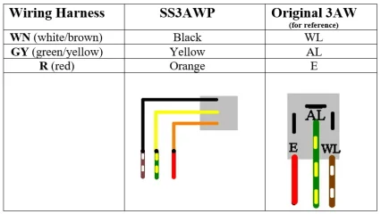
Yes., or the wiring to the WLA. One of the alternator wires must go to its input. I had a cool cat WLA on a 3 phase and it worked well.
 
Yes - they work well.

And as @maylar points out, you will be picking up on just one of your three phases.

Charging Voltage on 3-Phase Lucas w/Podtronics

Charging Voltage on 3-Phase Lucas w/Podtronics
 
@nomadwarmachine start by measuring your battery voltage with your engine off to determine whether or not your charging system is working.


With your engine switched off, and no consumers like coil or lights drawing any power you will see the voltage of your fully charged battery it’s value varies depending on the type of battery you have:
  • Lead acid (including gel, AGM, flooded and drycell) are 2.1 volts per cell, so you should see 12.6 volts when fully charged.
  • Lithium based (including lithium-ion, lithium polymer, LiCoO2, lithium cobalt oxide and LiFePO4) are 3.6 volts per cell, so you should see 14.4 volts when fully charged.
With a single phase alternator, at engine idle you should see the voltage at the battery drop to around 11 to 12 volts - in effect, you are taking out more than you are putting back in. This is by design.

With a three phase alternator, your are moving the charging band from 3,000rpm, down to nearer 1,000rpm.
so at engine idle with three phase, you should expect to see around 12 to 13 volts.


Holding your revs at between 3,000rpm and 4,000rpm you should see the voltage reading go up to around 14 to 15 volts.
Your podtronics is designed to short out your alternator coils when the battery charge target voltage of 14.2 is met.


Lucas alternators are rated as follows:
  • 5,000 rpm - single phase alternators provide 75% of their rated output
  • 2,400 rpm - three phase alternators provide 85% of their rated output


Anecdotal only, the original rm23 on my MK3 seems to kick out more than 75% of its rated output at 5k rpm. At 3400+- it balances the electrical load with 60 watt headlight, 8 watt taillight, 35 watt heated vest and analogue Boyer ignition ( 20 watts ?) So this is about 125 watts at 3300. I say it is balanced as the voltage monitor goes to green ( above 13.5v) and stays there as long as that rpm or above is maintained. I think that indicates at least a balance, if not a small charge happening.
Anyway, the load can be sustained at that RPM.

The original Lucas ad for the RM 24 3 phase alternator states the new 3 phase RM 24 produces " 85 % of rated output at 2400 rpm vs 75% for the RM21(120watt rating)" The graph with the ad shows the single phase RM21 making slightly more than its rated 120 watts at 5000 rpm.


Here are the results of an RM23 output test done by DynoDave in 09

Dave Comeau
Crew Chief
RM23 180W single phase
2 sections, 3 coils in series per section
test 1 ohm load /AC
1900rpm 9V 9amp =81W
2400rpm 11V 11amp =121W
2600rpm 12V 12amp =144W
3400rpm 13V 13amp =169W
4000rpm 14V 14amp =196W
open curcuit 40.7VAC


Glen
 
Last edited:
Thank you all! This community is incredible. Going to pull out the multimeter and set about testing this weekend. Will report back!
 
@worntorn apologies Glen, my anecdote came from the LAP guys who were producing under the Lucas name in the early nineties. They were the only performance specs they would part with.

I have no doubt that specs have changed between the original Lucas, LAP and of course the new Lucas which is Wassell.

I also have no doubt that the specs change depending on the batch of magnets that are used in the rotors, the make of the lacquered copper wire that is wound onto the stator poles and even the tolerance (air gap) between rotor and stator which I know from experience is tighter now than it was just a couple of years ago.


But that’s all by the by - hopefully @nomadwarmachine has some things to check, and we’ll be able to get him all up and running!
 
This is great info for those with lithium batteries which are more sensitive to low/high voltages
 
Just fired up the Norton on my WFH lunch break and connected the Battery Tender Voltage Reader to the pigtail. Reading 14.2V at 2K rpm with the halogen headlight off. Looks like the 3P Lucas & Podtronics are working here. If I switch the headlight on, the voltage drops into the mid 13Vs but noses back up to 14V as I rev the engine. Does this seem normal to everyone?

Throughout the test, the red assimilator light connected to my Cool Cat solid state unit remained lighted. Must be a mistaken connection? Going to pull off the tank tomorrow and check the wiring. Need to adjust the throttle cable anyway....
 
Yes - they work well.

And as @maylar points out, you will be picking up on just one of your three phases.

View attachment 16361

View attachment 16362

GTiller, I compared your CoolCat 3P diagram (#2) to my connections from the alternator to the Podtronics. I have all three of the yellow/green output wires connected to the Podtronics yellow wires. None of them is connected directly to the CoolCat assimilator. Should I add a connection directly off the one of the alternator output wires into the assimilator (i.e., a Y-shunt with one output to the Podtronics and one to the CoolCat)? If so, that makes me wonder what I hae connected to the CoolCat yellow right now....
 
@nomadwarmachine yes indeed.

You’ll need to tee off one of your yellows (any one of them, it doesn’t matter)

And connect that to the yellow lead of your CoolCat.


So to summarise:
  • two alternator wires connect directly to your podtronics
  • the third alternator wire connects to the podtronics AND the CoolCat
Hope this helps!
 
GTiller, I compared your CoolCat 3P diagram (#2) to my connections from the alternator to the Podtronics. I have all three of the yellow/green output wires connected to the Podtronics yellow wires. None of them is connected directly to the CoolCat assimilator. Should I add a connection directly off the one of the alternator output wires into the assimilator (i.e., a Y-shunt with one output to the Podtronics and one to the CoolCat)? If so, that makes me wonder what I hae connected to the CoolCat yellow right now....
The stock alternator 2 wires went to the rectifier, and one of those (green/yellow) also went into the harness and fed the WLA input. Easiest 3 phase setup is to run 2 of the Pod's yellow wires to the spade connectors for the old rectifier and add one additional wire from the stator directly to the Podtronics. If you've run 3 wires directly to the Podtronics you'll need to tap into one of those and connect it to the green/yellow wire that feeds the WLA.
 
GTiller, I compared your CoolCat 3P diagram (#2) to my connections from the alternator to the Podtronics. I have all three of the yellow/green output wires connected to the Podtronics yellow wires. None of them is connected directly to the CoolCat assimilator. Should I add a connection directly off the one of the alternator output wires into the assimilator (i.e., a Y-shunt with one output to the Podtronics and one to the CoolCat)? If so, that makes me wonder what I hae connected to the CoolCat yellow right now....
IMHO, better would be to throw away the assimilator and to install a madass140 oil pressure switch. The assimilator just tells you that the stator is doing something - not that your charging circuit is working. I much prefer to know I have oil pressure.
 
Status
Not open for further replies.
Back
Top