Another recommissioning project for me

Then the typical T140/T160 lower fork cap problem has materialised,
I'm wondering just how tight you'd have to tighten the fork bottom clamp bolts to crack those clamps? I've seen them broken before and like you say it's pretty common?

Unfortunately, this is usually the result of the incorrect torque figure of 23-25 lb. ft. for the (x2) spindle "cap bolts" (25 lb. ft. in the T140V manual) carried over from the previous two-bolt steel cap forks instead of for the (x4) alloy "cap nuts" of 15 lb. ft. corrected in the later T140E manual.
 
Unfortunately, this is usually the result of the incorrect torque figure of 23-25 lb. ft for the (x2) spindle "cap bolts" (25 lb. ft. in the T140V manual) carried over from the previous two-bolt steel cap forks instead of for the (x4) spindle alloy "cap nuts" of 15 lb. ft. corrected in the later T140E manual.
I've never used a torque wrench on these I'm wondering who would?
I have noticed them on people's bikes sitting uneven where they have tightened one side fully before the other!!
 
I've never used a torque wrench on these I'm wondering who would?

Neither have I and it's probably also a case of owners overdoing it, especially as there four fasteners.

I have noticed them on people's bikes sitting uneven where they have tightened one side fully before the other!!

Possibly the result of experiences with Japanese bikes that can have uneven cap faces that are supposed to be tightened so there's a gap only on one side.
Edit
Another recommissioning project for me
 
Last edited:
These parts are a casting and not really very robust, as LAB suggests, they’re likely to have been over tightened. I’ll assume billet replacements will be a better choice, I’ll invest in a pair for mine ‘just in case’
 
This beast is testing me at every turn of a spanner. It’s rather strange to know how a never-loosened nut and bolt can feel after nigh on 50 years. Let’s remove the silencers and exhaust system. The lh silencer grudgingly allowed itself to be taken off, and in doing so deposited a massive amount of rust in its place. The rh one will not move despite heat and copious releasing fluid. So I’ll take the front pipes, collector and silencer off as a lump. Then I found that the whole system has received a massive clout some time in its past, and when finally I managed to get it down to its component parts the collector is rusted through which accounts for the pile of rust. The owner thinks he’s got another system at home somewhere from when he created a Slippery Sam replica.
Another recommissioning project for me
 
I’ve stripped down the indicator switch unit to clean and lube it, all well and good. However, at some stage in its life with the USA the previous owner has decided to lose the correct 2 screws that holds the unit together. Both threaded holes have been butchered by adding a self-tapping screw and was held together with just the one. Grrrrr.

I am considering filling the holes carefully with JBWeld and then re drilling and tapping to a suitable size of thread, assuming I can find a tap that small I reckon my set will be too big. Perhaps I could go down the self-tapper route? The existing threads don’t match anything I’ve got, either too big or too small

is it doable? I don’t want to simply buy a replacement as they come with the wrong connectors. Thoughts?
 
I've successfully repaired the switch cluster threads before now with Lumiweld or HTS 2000.
 
I’m not really up to doing anything involving a heat source I’m afraid I’ll melt something or cause a fire.

I had another thought to open the holes and ‘glue’ a suitable sized small headed bolt inside, then add a nut to the outside to hold it all together.
 
I had another thought to open the holes and ‘glue’ a suitable sized small headed bolt inside, then add a nut to the outside to hold it all together.

Why bother with a bolt head? Why not just glue (JB Weld) a 'stud' in, perhaps with flats filed at the inner end?
 
My thinking, if you can call it that, was that a ‘head’ in at the end would not then want to try to unscrew if it was just a stud.
 
My thinking, if you can call it that, was that a ‘head’ in at the end would not then want to try to unscrew if it was just a stud.

That's why I suggested the flats as they should also key the stud into the 'glue' (JB Weld) although I'd expect JB to hold well enough on the threads alone.

Forks all successfully reassembled?
 
Er, I haven’t touched them. Once they were cleaned off they appear sound, and so rather than do too much that may not be needed they’re good for now.
 
I've never used a torque wrench on these I'm wondering who would?
I have noticed them on people's bikes sitting uneven where they have tightened one side fully before the other!!
ditto, only use a 1/4 drive socket on those, snug them up... (quickly checks gap)... gap is even :cool:
 
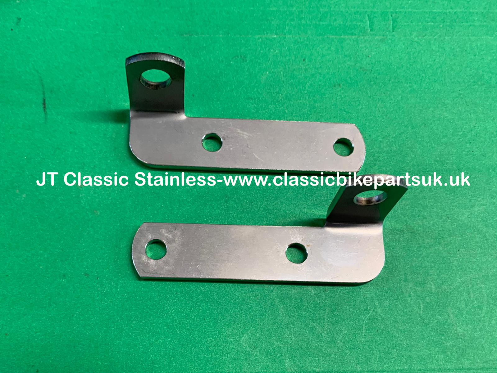
Something else a little bit strange I’ve found so far while working on this bike. The brake line from beneath the yoke is different to my set up. The metal formed pipe work is a different shape and fits to the lower yoke mounting, but then the end of the hose has a bracket with the bend the other way and then the solid pipe to the caliper is also different. The parts book I have shows no alternatives. Look at the pics as they may make more sense.
Another recommissioning project for me
 
I can't be much help with this as the original line had been replaced with a twin-disc conversion and braided hoses on my T160, however, the fork pipe support bracket with the angled lug at the top seems correct from brochures, road test pictures, parts diagrams, etc. but there's also a right-handed bracket (83-8062) for late twin-disc twins.


It’s only now I’ve realised it’s my bike that differs from the parts book. I’ll keep quiet 🤫
 
Nope, I won’t keep quiet, it’s slowly festering inside me. 45 years of parts supply has given me OCD when it comes to sorting out queries like this, I have to understand what’s going on.

And so, while watching England v Wales rugby it came to me in a flash. I know my bike had an incident in the past that caused it issues with the LH switchgear, the front lip of the mudguard, the headlamp brackets and indicator lamps.

So imagine that in addition, let’s assume it was a minor collision, that brake caliper bracket was also damaged, and its replacement happened to be the RH version off a T140 (like my indicator switchgear was) . That was fitted, albeit upside down, and while the hose had the necessary length - just - this made the pipe too long, and so it was bent to suit. It works, but right now it is niggling my OCD.

Now to find out where to get a bracket and a pipe :cool: Good, more exploration for me, I’ve come up with an few options.
 
And of course I can simply make up a new pipe from fittings and kunifer pipe.
 
I noticed the handlebar P-clamp lower hemispherical washers of both bikes seem to be fitted tapered side down which wouldn't be the usual way but could perhaps have been done to increase the handlebar rigidity in the metalastic bushes.
This should not be done with the top hemispherical washer, however, because the head of the P-clamp must locate in the washer's recess. If the upper washer is reversed and fitted 'sharp edge up' then it can cause the P-clamp to fracture.


Another recommissioning project for me
 
Never knew that. I had no pictures to work from and ‘assumed’ the correct way was how I’d done it. A bit of a PITA to correct both bikes :(

ho hum yet more to do. You know I can’t leave them be as they’ll be always on my mind.
 
Back
Top