Alternator clearance

Status
Not open for further replies.

Fast Eddie

VIP MEMBER
Joined
Oct 4, 2013
Messages
21,594
Country flag
I’m partially stripping the Trident Hunter at present.

I noted when removing the alternator stator (new ‘Lucas’ replacement fitted 2013) that it had been rubbing mildly on the stator.

When I fitted this I went to quite some trouble, using plastic bottle ‘shims’ and checking with a .010” feeler gauge.

So, I’m thinking that the contact may be due to crank flex at high rpm? I’m also thinking that more clearance would help.

I recall Stan Shelton (Triumph Tuning) saying “the rotor can be turned down .010” thus creating a .020” air gap resulting in less oil drag and less chance of metal particles getting jammed”.

My primary is dry, so oil drag isn’t a concern, but this raises the question, how much can the gap be opened up by without detrimental effect on the alternator.

I’ll at least do as Stan says and take .010” off, I’ve done that before, but can I take more? Does anyone know?
 
Exactly what I did recently with a brand new Lucas RM20 rotor.

We mounted it up in the lathe and blew air over it as we cut so that the filings were blown away from the magnets and the finish was perfect
 
Last edited:
Check the type of rotor that you have, Lucas made a batch in certain years that didn’t have welded magnets so that they kept expanding outwards at high revs. .020 is only a .010 cut on a lathe so it seems within limits.
 
Exactly what I did recently with a brand new Lucas stator.

We mounted it up in the lathe and blew air over it as we cut so that the filings were blown away from the magnets and the finish was perfect

Thanks for that, got more questions tho: Do you mean that you cut exactly .010” off? What was the gap when assembled? And how does it function?
 
Exactly what I did recently with a brand new Lucas stator.

We mounted it up in the lathe and blew air over it as we cut so that the filings were blown away from the magnets and the finish was perfect

There are no magnets in the stator. You must have been turning down the rotor.
 
How do magnets cut in the lathe??

On the Lucas rotors, there are soft iron laminated pole caps that sit on top of the magnets. So when turning a rotor, you are not actually cutting into the magnets you are cutting into the pole caps.

Peter Joe
 
@batrider yep - my bad, I corrected my brain-fart thanks

The rotor cuts easily in the lathe - certainly a lot softer than turning down say a stainless bolt.
We took it nice and slow as I was keen to maintain the best possible finish.
As @PeterJoe points out, it’s not the actual magnet it’s a cap.


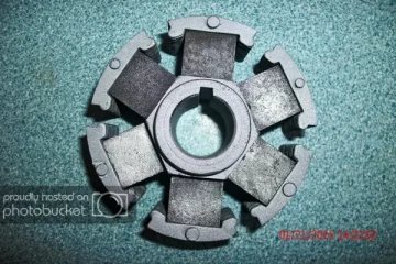
I found this pic on the web, which made me much more comfortable about machining the rotor.
Alternator clearance
You can see the shape of the caps means that nothing is going to come lose and fly off once the engine is running, even after removing some material from the OD.
They are held well and truly captive when potted up in the rest of the rotor material, which I assume is poured aluminium.


I measured my diameters in metric - sorry!
The rotor initially measured at 74.1mm
We turned it down to 73.9mm
It means I can now comfortably get a 12 thou feeler gauge all the way around between the rotor and stator.

We did this on a T120 Bonnie and the charging was perfect, so I’ve just done exactly the same on my project Norton.

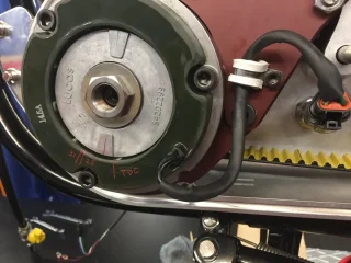
Alternator clearance
 
Interesting!

So, you took off .2mm, which is .008” isn’t it?

Therefore you gained .004” clearance.

Yet still only had .012” when you’d finished.

So, it would have only been .008” as supplied?

Factor in the fact that the stator is unlikely to be mounted perfectly concentric to the rotor, and there’s gonna be less in places. Which seems to support my thinking that a flexing crank would be enough to cause fouling.

Are these new stators a smaller ID compared to originals?

Do they have a properly round ID?

Can they be bored?
 
Correct both components were brand new:
rotor RM20 LU54202299
stator RM24 LU47244

I wasn’t happy with the clearance and actually sent them back to start with.
What I received as replacements were absolutely identical - so I can vouch for their consistency.

They do seem to be tighter versus the older ones I take off bikes - I’ve done several 3 phase upgrades now, and the air gaps between the rotors and stators I remove seems huge in comparison to the new components that go back on.


I chuck up the rotors in the lathe, and all the new ones are perfectly concentric.
And on the stators, the measurements between the opposing cores (the metal bits on the inside that you see poking through the resin) is spot on, which is about the best test for roundness I can do.
So the only thing I can call out is that the tolerances are tighter.
 
Thanks.

With your findings, and the reports of seized rotors and burnt out stators, I think you’re right about the redcuded air gap versus old original stuff.

Perhaps the new ones are made by suppliers more used to supplying for modern engines with less flexy cranks and cases?

I fitted a new stator to an old rotor. For what it’s worth, my old rotor measures 73.95mm as best as I can measure it, and I still had fouling.

I’m going for a .020” gap when I re assemble this one.
 
Rotors should be 74mm-not a big deal.
There are a few stators that are smaller than they should be.
Original and correct is 75mm, yet some years back I got some new ones that were 74mm.
It took me along time to realize why the seemed so close, and finally measured them. I will now open up the bore of the stator on the lathe to 75mm.
 
Status
Not open for further replies.
Back
Top