
lazyeye6
VIP MEMBER
- Joined
- Feb 28, 2014
- Messages
- 1,182
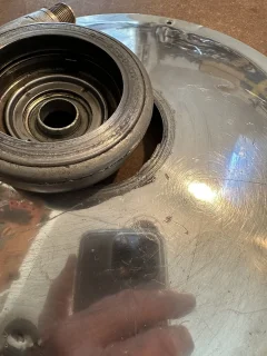
My recently acquired ‘’74 Interstate has posed some challenges. More on that in a future post. There is a slight interference between the nave plate and the Speedo sending unit. Not enough to restrict the independent operation of each, but a scraping sound can be heard. Photo depicts wear on each of the two items.
Any clue what might be causing this? Speedo sender doesn’t appear to be distorted at all.
Any clue what might be causing this? Speedo sender doesn’t appear to be distorted at all.


")