Speedo sending gear interference

lazyeye6

VIP MEMBER
Joined
Feb 28, 2014
Messages
1,144
Country flag
My recently acquired ‘’74 Interstate has posed some challenges. More on that in a future post. There is a slight interference between the nave plate and the Speedo sending unit. Not enough to restrict the independent operation of each, but a scraping sound can be heard. Photo depicts wear on each of the two items.
Any clue what might be causing this? Speedo sender doesn’t appear to be distorted at all.
 

Attachments

  • Speedo sending gear interference
    323DE033-1709-4F39-8A02-988E47928A1B.webp
    308.7 KB · Views: 121
Some help may be here ....>


Slick
 
Any clue what might be causing this? Speedo sender doesn’t appear to be distorted at all.
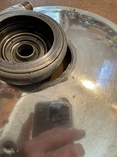
Your picture clearly shows the internal spacer has crushed the housing metal because a new housing would not have the depression around the top hat sleeve so that will not be helping matters and can result in the housing becoming distorted which might not be visible but could perhaps benefit from being pressed back into shape and a shim added on the inside to compensate for the reduced housing thickness.
 
My speedo drive had this issue. It made contact with the hub cover plate and leave the same gouge as it your picture. This is a fairly common issue and been discussed a lot in older threads. The most likely culprit is that the axle torque spec for 70 ft-lbs causes the drive casing to extrude outwards from the axle clamping area, which causes the outer casing area to move toward the hub cover and machine the gouge. Drive can be pressed back in a vise with some blocks of wood. Folks here now recommend 45-50 ft-lbs on the axle nut torque. This has solved issue for my mk2 bike.
 
Thank you all for on/point observations , ideas and the link.
Yes, this speedo gear is slightly distorted measuring 1.05” thick.
I will try pressing it and adding a shim.
 
My recently acquired ‘’74 Interstate has posed some challenges. More on that in a future post. There is a slight interference between the nave plate and the Speedo sending unit. Not enough to restrict the independent operation of each, but a scraping sound can be heard. Photo depicts wear on each of the two items.
Any clue what might be causing this? Speedo sender doesn’t appear to be distorted at all.

Another issue is that the sheet steel retainer [section which is rubbing] has been forced outward. This happens when an owner or mechanic pumps to much grease into the drive gear via the grease nipple. It can simply be tapped back in, once you've corrected this issue that Les pointed out.
 
Thank you all for on/point observations , ideas and the link.
Yes, this speedo gear is slightly distorted measuring 1.05” thick.
I will try pressing it and adding a shim.
The speedo drive should be flat on the outside. Get the "speedo drive spacer" (top hat) out of it, and if not flat, it can be made flat again with a little hammer work (hit the damned thing but not real hard). Then you may need a new drive spacer and don't tighten so much.
 
I've had my Mk2a since new. The top hat spacer was fitted directly into the wheel bearing spacer on the inside of the speedo drive. It was never fitted through the speedo drive unit.

The 'brim' provides the spacer to stop the speedo drive from touching the aluminium trim plate and the whole assembly will bolt up without causing a distortion of the speedo drive housing.

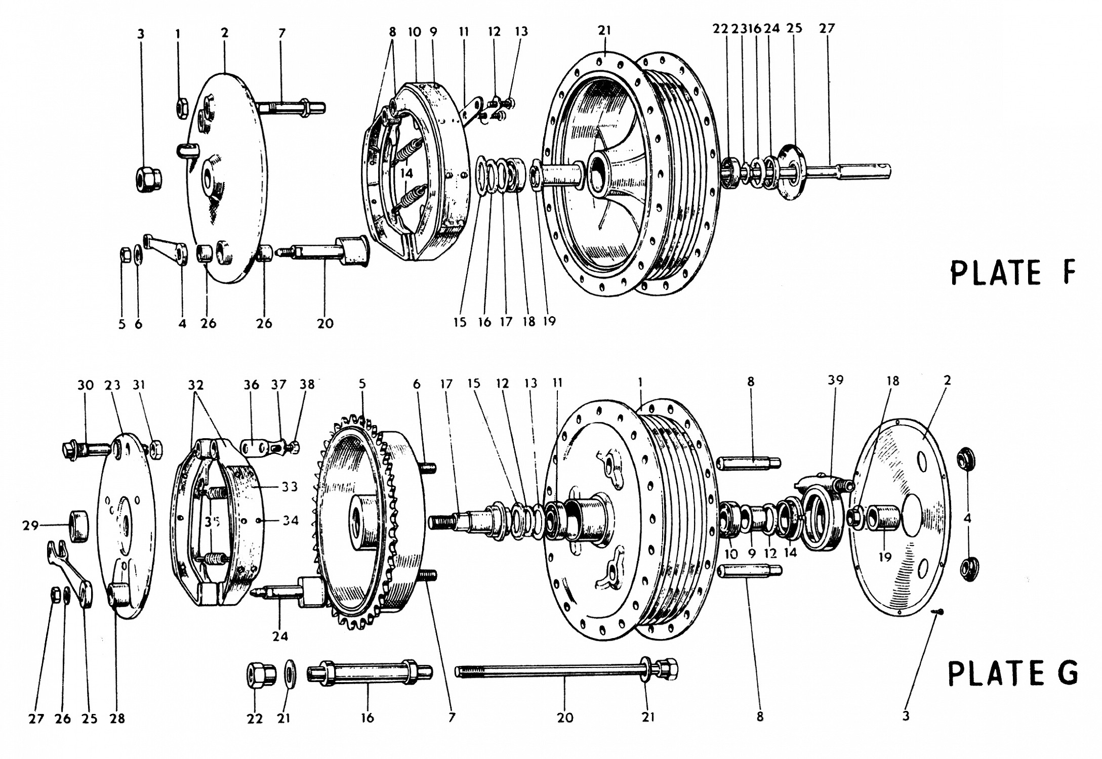
Norton built it right but the artist doing the assembly diagram showed the spacer in the wrong position leading to all the fun and games documented in this and other posts.
The job of 06.7629 SPEEDO DRIVE SPACER (NM 13270) (B2/660) is to fit the speedo drive to the axel as there is no speedo drive made specifically for the Norton axel. It cannot do it's job if not through the speedo drive.
 
I've had my Mk2a since new. The top hat spacer was fitted directly into the wheel bearing spacer on the inside of the speedo drive. It was never fitted through the speedo drive unit.

This has been discussed before (at least once).
https://www.accessnorton.com/NortonCommando/shim-on-speedometer-drive.26779/post-402042
Twice

The top hat spacer has to fit on the outside to reduce the 11/16" hole in the drive gearbox down to the 9/16" axle diameter. Without it, the drive gearbox would not be centred on the axle.


Norton built it right but the artist doing the assembly diagram showed the spacer in the wrong position leading to all the fun and games documented in this and other posts.

There's more than one drawing showing the top hat spacer on the outside of the speedo drive gearbox as far back as early Featherbed Dominator.
 
Last edited:
Yes. I described the same solution both times so I posted with some trepidation.

A little background - I assembled my Mk2a Commando from an ex- factory crate in Shirlaws Yard, Princes Street, Aberdeen in December 1975. The top hat spacer was located as I described.
My bike does not exhibit the problems described by so many including the OP here.

Regarding the requirement for centering that the external positioning of the spacer would help with : The rear brake plate has no centering spacer, it floats until aligned during the proper axle tightening procedure that we can all see in the manuals. Regarding the speedo drive, I have not had any damage to the aluminium cover plate, not have I had to heat and press the speedo drive housing to return it to the factory width despite the lack of a centering spacer. In 40,000 miles.

Re Drawings - As a piece of mischief , have alook at part number 24 on the Andover Norton Mk2a Oil Tank and Fittings drawings page. The screw fitting on a hose clamp do not look like that do they? See Part No 18. Small mistakes happen.

Anyway, thats more than enough from me.
 
Re Drawings - As a piece of mischief , have alook at part number 24 on the Andover Norton Mk2a Oil Tank and Fittings drawings page. The screw fitting on a hose clamp do not look like that do they?

There's no disputing there are errors on the drawings and not the first time the slightly incorrectly drawn hose clamp screw has been mentioned...
https://www.accessnorton.com/NortonCommando/speedo-cable-wrapped-around-axle.33557/post-546832

The scavenge hose passing through the "Oil Pipe Retention Clip" item 22 on that drawing is another but the top-hat spacer doesn't appear to be one of these errors because the general consensus is that it goes where it's drawn on every parts diagram back to the early Featherbed Dominator so can't be a one-off error.

: The rear brake plate has no centering spacer, it floats until aligned during the proper axle tightening procedure that we can all see in the manuals.
Yes, with the brake applied and is done to equalise the contact of each shoe against the drum which could result in the brake plate being set slightly off-centre and why the brake plate is a loose fit on the (dummy) axle.
 
Last edited:
Nothing ventured, nothing gained. I did press the sender back to it's intended thickness dimension (1.15" to .085") using my shop vise
and two blocks of hardwood. It now has quite sufficient clearance to avoid interference with the nave plate. HOWEVER this procedure
is fraught with risks. Yes, it worked quite well and now the internal drive ring spins quite freely as opposed to moderate resistance
before doing it. But, the process of pressing back to the original shape resulted in the front and back surfaces being not quite parallel
with each other, thus creating a slight wobble. I expect that the wobble might be corrected when the axle is torqued down. We shall
see. Perhaps a machinist with a perfectly parallel set of vice jaws wider than the width of the sender could achieve more precise
results. Blocks of wood are prone to distorting during this process as well. Blocks of steel might be better. We shall see how long
it lasts.:)
Sounds bassackwards I know but I remove the spacer, lay them flat with the bow up and hit the center with a hammer to get it back to flat. Seems to work with no issues. I'm assuming because the entire unit is supported.
 
But, the process of pressing back to the original shape resulted in the front and back surfaces being not quite parallel
with each other, thus creating a slight wobble. I expect that the wobble might be corrected when the axle is torqued down.

I somehow doubt it will...

Blocks of wood are prone to distorting during this process as well...

Yes, which was why I used a vice/vise with a sheet metal jaw protector to support the back of the housing and a square drive socket on the outside to press it back into shape.
 
Back
Top