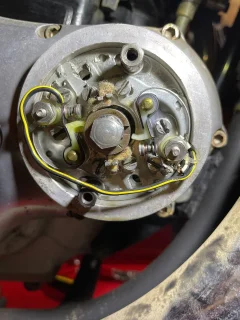
Points cam scribe mark not lining up with points heel

Joined
Sep 16, 2023
Messages
9
Country flag
Hello everyone!

I have a 1973 Norton Commando 850 and I have been trying to set the ignition timing by adjusting the points.

Here is my current process:
1. Take spark plugs out and remove exhaust and intake valve covers
2. Remove the port window on the primary chain case cover that displays the static degree plate and engine timing mark
3. With the bike in neutral, slowly move the kick until I see the left piston's intake opens and closes and piston rises
4. Now that I believe I am on the compression stroke of the left cylinder, I look for the timing mark in the primary chain case and align it on the 28° mark on the black plate by putting the bike in gear and turning the rear wheel
5. Once the timing mark is perfectly on the 28° mark, I now move to the points assembly
6. In the points assembly, I look to see if a points set heel is in-line with the scribe on the points cam and set gap

This is where I find the problem, the points cam scribe mark is far off from the points heel, and there is not enough adjustment capabilities on the points assembly and plate to get them to align.

Why would this happen?
Why would things get so far off?
Is this a normal problem over time?
Am I messing up the procedure somewhere?

Attached is a photo of how far off the scribe line is from a heel, this is with one piston at (to the best of my knowledge) BTDC at the 28° mark on the compression stroke.

Thank you all for your time!
 

Attachments

  • Points cam scribe mark not lining up with points heel
    IMG_1592.jpg
    332.8 KB · Views: 135
I have a 1973 Norton Commando 850 and I have been trying to set the ignition timing by adjusting the points.

Firstly, the ignition timing is done after setting the points gaps.

You've gone wrong here:
6. In the points assembly, I look to see if a points set heel is in-line with the scribe on the points cam and set gap

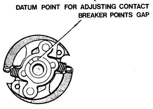
The gap setting and the ignition timing are entirely separate procedures so you need to set both gaps first by lining up one heel with the line on the points cam and setting the gap, then rotate the camshaft (by turning the crankshaft one full turn) and setting the other points gap. The points gaps should not then be altered.
Once the points gaps are set then the scribed line has no further part to play in the setting of the ignition timing.
Points cam scribe mark not lining up with points heel


Ignition timing is done by adjusting the backplate (for both sets) or each sub-plate as mentioned in your previous thread.

Attached is a photo of how far off the scribe line is from a heel, this is with one piston at (to the best of my knowledge) BTDC at the 28° mark on the compression stroke.

The points gaps, therefore, cannot be set correctly or I think you are not following the correct procedure due to a misunderstanding of what the scribed line is used for.

Also in order to set the ignition timing the points cam must be held/locked in the fully advanced position first.
 
Last edited:
The gap setting and the ignition timing are entirely separate procedures so you need to set both gaps first by lining up one heel with the line on the points cam and setting the gap, then rotate the camshaft (by turning the crankshaft one full turn) and setting the other points gap. The points gaps should not then be altered.
Once the points gaps are set then the scribed line has no further part to play in the setting of the ignition timing.
Points cam scribe mark not lining up with points heel

Oh man that makes much more sense. Okay! So, I simply line the scribe with a point heel and set that points gap (since the scribe represents the highest part of the lob on the points cam), then spin the scribe to the next heel, and set that gap. Correct?

Then, once that is done, I can connect a strobe light and flash it in the primary chain case port window to see how the timing is. If I notice it being off, then I loosen the points assembly plate or points plates to attempt to adjust to get the strobe lighting when the timing mark is right on the 28° mark.

I am doing more research but I have not found a very clear step-by-step for ignition timing with the original points yet. However, I am still digging.

I am confused on this point:

Also in order to set the ignition timing the points cam must be held/locked in the fully advanced position first.

My current blurred understanding this is as follows:

Behind the points assembly plate is the spring loaded points cam unit, I believe known as the Timing Auto Advance Unit.
It sounds like you are saying that when setting the ignition timing, this Auto Advanced Unit springs and cam rotation should be as expanded as possible (simulating a high RPM running engine).

This obviously means that you are holding/locking the Auto Advanced Unit in fully advanced position while the bike is not running and you are try to set it all statically.

Finally, this brings my mind to imagine the correct procedure for points gap and timing would be as follows:
1. Take a deep breath, and be happy its a Norton you get to bond in struggle with
2. First, set points gap by ignoring piston stroke and crank degree of turn, instead, simply line the scribe on the points cam with a points heel and set that gap, spin engine to get scribe on next points heel and set that gap
3. Now the points gaps are set, its time to check ignition
4. Remove the exhaust and intake valve covers as well as the primary chain case port window to timing degree plate and mark
5. Rotate engine to get one piston on compression stroke (watch intake open close and piston rise in that cylinder to find this)
6. Go to port window and with bike in gear, rotate wheel to get the timing mark at the 28° mark which is BTDC
7. Lock the Auto Advanced Unit/points cam in its most full open rotated position ("fully advanced position")
8. Make sure a strobe is connected
9. Loosen points plate and rotate counter clock-wise, then clock-wise slowly until the points just open and trigger the strobe
10. For the next cylinder, check to see that when you roll the timing mark at 28° the strobe fires

I am not very confident on steps 9 and 10 yet, but that's where my head is at.

My biggest points of confusion is how to check/setup the correct points assembly positions.
When the timing mark is at the 28° mark and the Auto Advanced Unit is in fully advanced position. How do you move or adjust the points assembly to the correct position for correct timing? Once one cylinder is done, is the adjustment on the points assembly for the next cylinder different (since you do not want to disturb the first one you just set)?
 
Oh man that makes much more sense. Okay! So, I simply line the scribe with a point heel and set that points gap (since the scribe represents the highest part of the lob on the points cam), then spin the scribe to the next heel, and set that gap. Correct?

Yes,

Behind the points assembly plate is the spring loaded points cam unit, I believe known as the Timing Auto Advance Unit.
It sounds like you are saying that when setting the ignition timing, this Auto Advanced Unit springs and cam rotation should be as expanded as possible (simulating a high RPM running engine).

Yes, the points cam must be *rotated and locked* in position because the static ignition timing is set at the fully advanced (28° BTDC) position.
*(See Factory Manual, C38, "Ignition Timing Procedure - Engine Static", 5, 6 &7.)

Finally, this brings my mind to imagine the correct procedure for points gap and timing would be as follows:
1. Take a deep breath, and be happy its a Norton you get to bond in struggle with
2. First, set points gap by ignoring piston stroke and crank degree of turn, instead, simply line the scribe on the points cam with a points heel and set that gap, spin engine to get scribe on next points heel and set that gap

:) Correct.

3. Now the points gaps are set, its time to check ignition
4. Remove the exhaust and intake valve covers as well as the primary chain case port window to timing degree plate and mark
5. Rotate engine to get one piston on compression stroke (watch intake open close and piston rise in that cylinder to find this)
6. Go to port window and with bike in gear, rotate wheel to get the timing mark at the 28° mark which is BTDC
7. Lock the Auto Advanced Unit/points cam in its most full open rotated position ("fully advanced position")

Yes, when setting the ignition timing statically.

8. Make sure a strobe is connected
9. Loosen points plate and rotate counter clock-wise, then clock-wise slowly until the points just open and trigger the strobe
10. For the next cylinder, check to see that when you roll the timing mark at 28° the strobe fires

No. If you have a strobe then you don't remove valve covers (step 4, as you will be running the engine) or steps 5, 6 & 7. They are for static timing.

If you have a strobe then all you need to do is set the ignition timing statically so it's close enough for the engine to be started.
The actual timing of each cylinder can then be set using the strobe by revving the engine until the auto advance reaches/exceeds full advance RPM and then adjusting the backplate or the sub-plates.

Well sir that sounds like by far the best way to do it. So I will be getting my hands and tools close to this fastly spinning points cam to move the backplate or subplates? If that is the case, then I believe I have the whole picture here, and am now very excited to get this set perfect.

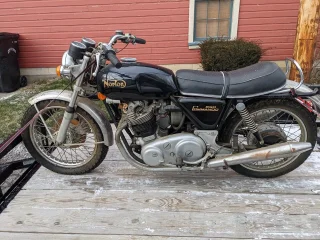
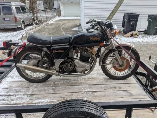
Little background, this is 1974* Norton that I purchased from the original owner and had been sitting in a garage since 84. Was missing valve covers and the gear box cover, here's it on the way home.
 

Attachments

  • Points cam scribe mark not lining up with points heel
    1622.JPEG
    538.1 KB · Views: 109
  • Points cam scribe mark not lining up with points heel
    1621.JPEG
    572.3 KB · Views: 111
Well sir that sounds like by far the best way to do it. So I will be getting my hands and tools close to this fastly spinning points cam to move the backplate or subplates?

Yes, obviously it's trickier to adjust the sub-plates with the engine running (at idle RPM) than it is to adjust the back plate.
Alternatively, stop the engine to make the adjustment then restart the engine, recheck, and repeat as necessary.
 
Last edited:
This procedure for points is detailed in the workshop guide, available as free download in the Technical Informatiom sticky thread at top of this forum.
 
This procedure for points is detailed in the workshop guide, available as free download in the Technical Informatiom sticky thread at top of this forum.

I think dlagrange has a copy of the (what I assume to be the factory?) "manual" as that was mentioned in post #11 of the "No spark left side etc..." thread) hence my references to the relevant sections in previous posts.
 
I used to have a very specific washer that I could use to lock the AAU in the fully advanced position to support static timing. It bore down on the points cam but the hole was wide enough to avoid the part of the shaft that the 'correct' washer bore down on. Once I was reasonably happy with the static timing the correct washer would go back on and the AAU was free to move in response to the laws of nature. There was no source to procure this washer, it was just something I found in my collection of old fasteners.
My two remaining Norton projects feature an electronic ignition on one and a magneto on the other, no more points for me.
 
Back
Top