gpzkat
MEMBER
- Joined
- Sep 2020
- Messages
- 873
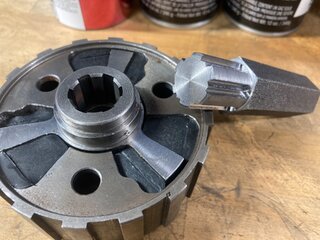
I don't have my bike in my garage, so I can't look (son borrowed it), but I found this for PN 030237A little progress this weekend, seasoned with a healthy dose of frustration. I broke a compression ring Friday night while rushing, luckily CBS is nearby and they saved me with new rings on Saturday. Again, while rushing, one of the oil ring expanders got loose on me, separated and launched the little connecting wire into the abyss of my garage, setting off a fruitless all day search/garage clean out. Today I mixed the old tech 3-piece oil rings with the new tech coated compression rings and was able to claim success.
Also swapped the gearbox cam plate to fix the awful GP shift pattern, checked initial cam timing (needs a few more degrees) and finalized the exhaust mounting.
Does anyone have the long footrest engine plate spacer tube handy? I need a measurement of that spacer - I made mine at 3-11/16” which matches the width of everything above it but it seems to pinch down to 3-5/8” at the lowest 5/16” crankcase stud. It doesn’t make sense to me and I’d like to know what the original spacer measures before I make any changes.
Chris
https://www.walridge.com/product/sp...otrest-rod-and-centrestand-spacer-g15-models/
Seems to fit the bill, measurement and location-wise, but it's not called out for the N15CS, prob just a miss in the book, since it calls out the G15CS.