
Thanks for visiting Access Norton
- Guest view limit reached
- Create a free account (more details)
- Already a member? Click here to login
You are using an out of date browser. It may not display this or other websites correctly.
You should upgrade or use an alternative browser.
You should upgrade or use an alternative browser.
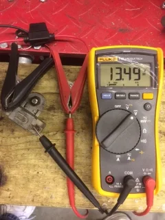
5.75 volts
- Thread starter PJFlynn
- Start date
- Status
- Not open for further replies.
PJFlynn said:5.75 volts at points is this enough juice to fire plugs. 71 commando working on electric 4 2 months replaced everything I can think of 12.48 at battery
Something is wrong somewhere.
You should have 12.48v at the points.
Good battery ?
You tried disconnecting the zener ?
And the blue thingy.
Is the headlight lit up. ?
Bad connection in the wiring or switch somewhere ??
Really bad connection....
by-pass the kill switch in the handlebars, the switch routes power through it to the ignition and when you push the button it interrupts the feed, the points inside get corroded and pass less and less voltage. I run a switching relay from the battery to the ignition and use the kill switch to trigger the relay. a relay will work on the switching side with quite a low voltage.
Deets55 said:Doesn't the ballast resistor drop the voltage for the coils and points down to 6 volts on a standard ignition circuit?
Thats an interesting question.
It drops the voltage across the coils, but is the voltage drop already at the points ?
Be funny if we were pontificating over a std ignition 'feature'.
Might break out the multimeter and have a looksee.
I can't remember if an 850 even has a ballast resistor.....
Good question above too about whether it actually produces a good spark.
Deets55
VIP MEMBER
- Joined
- Oct 3, 2013
- Messages
- 1,645
Rohan said:Deets55 said:Doesn't the ballast resistor drop the voltage for the coils and points down to 6 volts on a standard ignition circuit?
Thats an interesting question.
It drops the voltage across the coils, but is the voltage drop already at the points ?
Be funny if we were pontificating over a std ignition 'feature'.
Might break out the multimeter and have a looksee.
I can't remember if an 850 even has a ballast resistor.....
Good question above too about whether it actually produces a good spark.
I believe it drops the voltage across both. I don't have a wiring diagram for that year but my 75 shows that the points and coils are after the ballast. Pretty common system it helps the points last longer.
lcrken
VIP MEMBER
- Joined
- Mar 15, 2009
- Messages
- 5,063
Ballast resistor and coil are not drawing current when the points are open, so no voltage drop there. Except for transients when power is switched, you should see 12 volts at the points when they are open and 0 volts when they are closed. Something in your ignition circuit has a resistance that is reducing the voltage at the points. Could be a corroded connector or switch. Best way to find it is with a voltmeter/multimeter. Start measuring the voltage at the battery, and continue measuring at points along the circuit till you get to the points (switch, at the coils, etc.), and see where the voltage drops. You can trace the path of the circuit from battery to points on the wiring diagram in the service manual to identify where to make the measurements. If it's all good up to the points, suspect the condenser/capacitor across the points. If it has partially shorted internally, it can provide a resistive path to ground and reduce the voltage at the open points.
Ken
Ken
Deets55
VIP MEMBER
- Joined
- Oct 3, 2013
- Messages
- 1,645
lcrken said:Ballast resistor and coil are not drawing current when the points are open, so no voltage drop there.
Ken
Ken,
I have always used a test probe with a light whenever I tested points. whether it was a car, motorcycle or what not. I would just hook the alligator clip to the frame and use the probe to check the points and observe the light. In all the time I have been doing that I never realized the ballast resistor did not start causing resistance until it warmed up. I just assumed that since ( in engines with an electric starter) there is a bypass loop in the start circuit that supplies full battery voltage to the coils/points when the key (or button) is activated, that the ballast resistor was already doing its job. Damn, I just learned something new.
I now stand corrected.
Pete
- Joined
- Nov 20, 2004
- Messages
- 21,090
lcrken said:Ballast resistor and coil are not drawing current when the points are open, so no voltage drop there. Except for transients when power is switched, you should see 12 volts at the points when they are open and 0 volts when they are closed.
To see full battery voltage at the points requires both sets of points to be open otherwise the current draw from the closed points/coil circuit causes a drop in voltage across the 'open' set (even without a ballast resistor as the coil alone will do it).
lcrken
VIP MEMBER
- Joined
- Mar 15, 2009
- Messages
- 5,063
Deets55 said:lcrken said:Ballast resistor and coil are not drawing current when the points are open, so no voltage drop there.
Ken
Ken,
I have always used a test probe with a light whenever I tested points. whether it was a car, motorcycle or what not. I would just hook the alligator clip to the frame and use the probe to check the points and observe the light. In all the time I have been doing that I never realized the ballast resistor did not start causing resistance until it warmed up. I just assumed that since ( in engines with an electric starter) there is a bypass loop in the start circuit that supplies full battery voltage to the coils/points when the key (or button) is activated, that the ballast resistor was already doing its job. Damn, I just learned something new.
I now stand corrected.
Pete
It's not exactly a case of the ballast resistor not causing resistance until it's warmed up. The ballast resistor has enough resistance when cold (around 3 ohms usually) to reduce the voltage to the coil down to the 7 to 9 volt range. With the electric starter models, it would be even lower while the starter is operating, hence the bypass circuit on the MK3. The ballast resistor primarily functions as a current limiter. As the system draws more current, it heats up and offers more resistance, limiting current flow through the coil. Taking the ballasts out with no other changes will usually result in fairly quick failure of the original 6 volt Lucas coils.
What I was trying to say was that when measuring voltage at the points with the points open, there is no path to ground, meaning there is no path for current to flow through the circuit. With no current, there is no voltage drop at the coils, ballast, wiring, etc., so the measured voltage at the points should be the same as at the battery. If it is not (as in the OP's case), something in the circuit is providing a resistive path to ground, as in a leakage path in the ignition switch, kill switch, ballast, coil, wiring, etc. That's why I suggested checking the voltage along the circuit, starting at the battery and ending at the points.
As an aside, for those with a Harbor Freight store nearby, they regularly include a coupon for a free multimeter in their adds, and it's only something like $10 otherwise, so not much excuse for not having one. It is extremely useful for chasing down electrical gremlins. I've been using one of them for years now with no problems. As best I can tell, it is just as good for my purposes as the more expensive ones.
Ken
lcrken
VIP MEMBER
- Joined
- Mar 15, 2009
- Messages
- 5,063
L.A.B. said:lcrken said:Ballast resistor and coil are not drawing current when the points are open, so no voltage drop there. Except for transients when power is switched, you should see 12 volts at the points when they are open and 0 volts when they are closed.
To see full battery voltage at the points requires both sets of points to be open otherwise the current draw from the closed points/coil circuit causes a drop in voltage across the 'open' set (even without a ballast resistor as the coil alone will do it).
True. Any load on the battery (lights, closed points, bad zeners or rectifiers, wiring shorts, etc.) will also reduce the voltage measured at the battery. I probably should have just said to start with a measurement of the battery voltage with the ignition switch on, and then proceed to measure voltages along the circuit path to the open points to see where the voltage drops. For an open circuit measurement like this, any voltage drop along the circuit indicates a fault.
Ken
Deets55
VIP MEMBER
- Joined
- Oct 3, 2013
- Messages
- 1,645
Bench test with a power supply
Well after a couple of quick tests I know less than when I started. :shock: Perhaps the 1156 bulb did not draw enough amps?
If anything this verifies Ken's statement that there should be 12 volts at the points with both sets open (LAB). So the OP probably has a big voltage drop somewhere in is system
Attachments


Deets55
VIP MEMBER
- Joined
- Oct 3, 2013
- Messages
- 1,645
L.A.B. said:I can't see exactly what you are doing in the last photo but it looks as if you could still be measuring the 'supply' voltage?
Les,
1) Negative from power supply to one side of ballast (point A)
2) other side of ballast to lead on 1156 bulb
3) other bulb lead to positive power supply (point B)
This put ballast and bulb in series between power supply leads.
I measured across point A to point B.
Looking at it now I probably should have gone from bulb lead to positive power supply w/ meter in series with bulb and ballast.
- Joined
- Nov 20, 2004
- Messages
- 21,090
Deets55 said:1) Negative from power supply to one side of ballast (point A)
2) other side of ballast to lead on 1156 bulb
3) other bulb lead to positive power supply (point B)
This put ballast and bulb in series between power supply leads.
I measured across point A to point B.
Looking at it now I probably should have gone from bulb lead to positive power supply w/ meter in series with bulb and ballast.
Move the negative probe over to the other (lamp) side of the ballast resistor and compare the volt reading with the first.
Then, check between the two ballast resistor terminals.
Deets55
VIP MEMBER
- Joined
- Oct 3, 2013
- Messages
- 1,645
L.A.B. said:Deets55 said:1) Negative from power supply to one side of ballast (point A)
2) other side of ballast to lead on 1156 bulb
3) other bulb lead to positive power supply (point B)
This put ballast and bulb in series between power supply leads.
I measured across point A to point B.
Looking at it now I probably should have gone from bulb lead to positive power supply w/ meter in series with bulb and ballast.
Move the negative probe over to the other (lamp) side of the ballast resistor and compare the volt reading with the first.
Then, check between the two ballast resistor terminals.
I'll try that tomorrow, not home right now.
Thanks Les
Deets55
VIP MEMBER
- Joined
- Oct 3, 2013
- Messages
- 1,645
L.A.B. said:Deets55 said:1) Negative from power supply to one side of ballast (point A)
2) other side of ballast to lead on 1156 bulb
3) other bulb lead to positive power supply (point B)
This put ballast and bulb in series between power supply leads.
I measured across point A to point B.
Looking at it now I probably should have gone from bulb lead to positive power supply w/ meter in series with bulb and ballast.
Move the negative probe over to the other (lamp) side of the ballast resistor and compare the volt reading with the first.
Then, check between the two ballast resistor terminals.
Attachments

- Status
- Not open for further replies.
Similar threads
- Replies
- 10
- Views
- 773
- Replies
- 9
- Views
- 969