The Sifton 480 - Monster of all Norton cams

Status
Not open for further replies.
Joined
Nov 26, 2009
Messages
3,055
Country flag
The biggest cam you can get for a Norton is the Sifton 480

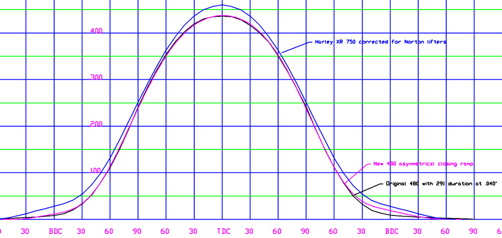
It has .435” lobe lift. Some are afraid to use it because it puts so much stress on the valve train. Flank acceleration is very high and cannot be avoided without stretching the duration too far. You can’t increase the spring pressure too much or you will only put more wear on the valve train. But you can reduce the closing jerk so the valves won’t crash down too hard and cause destructive valve bounce. This will enable it to revv higher than the original 480 while still avoiding valve clash. The idea is too build a high output 9000 RPM 750 short stroke land speed racer.

I don’t know if there is anything you can do to get such a cam to revv so high but we will try. Other cam designs have incorporated the smooth ramps and will revv to 9000 but they don’t have as much lift or acceleration as the 480. Too much spring pressure would again add strain to the mix. A tapered spring with about 150 lbs seat pressure will be used. But heavier large diameter valves with add to the problem. Heavy stock Norton lifters are out of the question. Lightweight BSA lifters will be used because this is what the cam was originally designed for (and Triumph lifters) and the lighter weight will help with valve control.

Its an asymmetrical profile with a closing ramp that is longer than the opening ramp.

The numbers are being sent off to the cam grinder and the new cam will have to prove itself on the dyno.

The image below shows the original 480 compared to the new asymmetrical 480 with a smoother closing ramp. The HD XR 750 cam is thrown in for comparison.
The Sifton 480 - Monster of all Norton cams
 
Last edited:
How about using titanium valves? As a race motor it does not sound like you are expecting this motor to last for years and years any way.
 
Yes on Titanium valves. They feel amazingly light in the hand compared to steel valves. Some people are afraid to use them because they think they will break and that can happen with harsh ramp cams and skinny stems, but with the smoother closing ramp, breakage should not be a problem if you stay with 5/16" stems. Look at the Harley race cam profile in the image above and you will see the long ramps provided to reduce valve closing impact stress. You can get HD XR 750 Titanium valves and they are good for a season. I checked them and they will work in a Norton with a modification at the tip. Problem is they are expensive and I am not the one deciding on the valves for this racer.
 
Last edited:
When you fit a race cam to a standard motor, you usually get an increase on torque right across the usable rev range, the top end of which is often higher. However with a Commando engine, the usable revs are usually limited by the strength of the bottom end. So getting more midrange power is more important than getting top end. With an inertia dyno, how good is it at measuring differences in mid-range torque ? In my own situation, I do not use a dyno. I only know I have an improvement when I can raise the gearing and the bike accelerates the same or faster. The difference it makes when racing usually occurs at the ends of the straights - you find that the bike does not run out of legs - so you don't get blitzed so often. There is a limit to how fast you can accelerate out of corners by lowering the gearing. With a Commando-based bike, a riders' circuit is always better then a power circuit. But that bit at the ends of the straights is always a problem.
 
Acotrel

This cam is all about top end and maximum HP. We don't care about accelerating out of corners because we are only interested in top speed and there are no corners on the salt flats.
 
Hi jim,

Have you thought (i did not follow deeper in the progress of your topic) about contacting 3M for their metal matrix pushrods in order to get the valve train lighter?
Regarding the Ti valves i could imagine that some V8 ti exhaust valves could fit which are most likely quite cheaper then the xr valves or norton custom types and have imho highly likely already a tulip better suited for mid to high lift flow in particular with xr/downdraft style portd. Seats would have to be anyways changed to Be or ampco45.

All the best and keep up your great informative work.

Kind regards

Christian

Ps: edit: i have to study the diagram a little but the Ic@1mm with 65degrees sounds like a reasonable number given pushrod flex etc without knowing right now what rocker ratio is.
 
Last edited:
Christian

I've checked into the matrix alum but haven't jumped on it. The high strength 2024 aircraft alum I'm using now is working very well with no failures so far. Rocker ratio is standard Norton 1:1.13 The biggest weight savings would be Ti valves but I'm not the one making that decision on this motor.
 
Hi jim,

Have you thought (i did not follow deeper in the progress of your topic) about contacting 3M for their metal matrix pushrods in order to get the valve train lighter?
Regarding the Ti valves i could imagine that some V8 ti exhaust valves could fit which are most likely quite cheaper then the xr valves or norton custom types and have imho highly likely already a tulip better suited for mid to high lift flow in particular with xr/downdraft style portd. Seats would have to be anyways changed to Be or ampco45.

All the best and keep up your great informative work.

Kind regards

Christian

Ps: edit: i have to study the diagram a little but the Ic@1mm with 65degrees sounds like a reasonable number given pushrod flex etc without knowing right now what rocker ratio is.


I contacted 3M some years back about the metal matrix pushrods, and they referred me to Smith Brothers, who made some pushrods for Harley drag bikes with the material. Somewhere on the forum I posted the details, but I haven't found the post yet. The bottom line is that the problem is machining the tubes. You have to use diamond tooling to cut the matrix material, and SB said it just got too expensive because the small diameter diamond reamers broke too easily. As far as I know SB are the only ones to ever make pushrods from the material, and only for the Harleys.

3M supplied them in 12" lengths, and they were pretty pricey too.

Ken
 
hi ken,

crap i would have loved to use those tubes sooner or later on my LM2.
On the other hand i think the guzzi has the pushrod caps over the tubes not pressed into them, but i assume there is no room for such measures in the tight space of the Commando head and commando jug.

kind regards

christian

@jseng1:

Would you be so kind and could post the numbers @1mm for intake and exhaust as im having somewhat troubles (slightly legasthenic, no im not kidding) to go through your diagram on the absisses axis.
Also would you have a diagramm with both curves in it??
I always love to follow serious cam topics!

Thanks a lot and kind regards

Christian
 
Last edited:
The other problem with the 3M MMC tubes was that they were only available from 3M (back in 2003, when I looked into them) in 3/8" OD with .147" wall thickness, making them significantly heavier than the .062" wall stock Commando rods or typical aftermarket .049" and .058" wall rods.

Ken
 
Acotrel

This cam is all about top end and maximum HP. We don't care about accelerating out of corners because we are only interested in top speed and there are no corners on the salt flats.

You might have a lot of top end power, yet in practice never get there if the run-up is not long enough. Perhaps you might be better using a very close ratio gearbox with that cam when on the salt ? That way you could keep the revs higher until you reach top gear and just lurch off at the start .
 
Christian

Here's the two curves. I hope its what you wanted.
The Sifton 480 - Monster of all Norton cams


I don't have the numbers in metric. Not ready to post them anyway.

The TDC lines in the graph mean nothing because I locate that at the peak of lift when comparing cams for visual reference. Ideally the cam gets about 2 degrees advance from an even split.
 
Last edited:
You might have a lot of top end power, yet in practice never get there if the run-up is not long enough. Perhaps you might be better using a very close ratio gearbox with that cam when on the salt ? That way you could keep the revs higher until you reach top gear and just lurch off at the start .

We normally have a one mile run-up for bikes under 175 mph, and a two mile run-up for bikes over 175 mph. That's more than enough for most Norton-powered bikes to get into the power band in top gear. It can be an issue with bikes like the turbo Hayabusas that have serious traction problems trying to get up to the power band in higher gears. Not really disagreeing with you here. A close ratio gearbox is definitely a good idea for landspeed racing, at least in the upper gears.

Ken
 
I would not have the nerve to attempt a land speed record using a Commando motor. When my motor is running at near a peak of even 7000 revs, I get very apprehensive. I really don't even like big race circuits, and the salt would be too much for me. On a short circuit in a good handling bike, a Commando motor can be excellent.
 
JS
the Sifton 480 was already asymetrical before you started playing with the ramps, your post however does raise a question, just how much valve lift is really necessary for top performance at 9000 rpm with a 750 short stroke Commando at a land speed record attempt ?

Most will be aware that the lift is necessary in order to obtain a reasonable period where the valve is open for maximum flow potential, the most often used yardstick being 25% of the valve seat inner diameter.

The other problem is how to arrange the cam lobes for best results. Norton and BSA are both restricted by having all cams on one shaft, whereas Triumph, Matchless and Enfield have separate camshafts. Tom Sifton made his choice years ago, and most probably his choice would still be considered a good one, but without any means of adjustment, getting it wrong could be a disaster.

Others may have attempted to increase the valve lift beyond .480" in the past, and likely may have been sucessful, but to my knowledge only Tom Sifton's 480 cam has survived to still be considered for top performance events such as that which JS is preparing for
 
@jseng1
thanks a lot yup thats what i wanted pretty much, now i have to study a little bit the diagram as im not used to cams with such massive Io-advance.

@acotrel
not being a commando expert but i would not see too much of a problem considering that, to my knowledge, one of the current recordholders is the team around tom mellor and the two bob´s

@Snotzo
usually depending on the throat area and the SSR characteristics i go up to about approx 30% as that also usually lifts the valves reasonably fast to their sweet spot (no shrouding) and leaves a clear flow path.

the thing im wondering about if anybody ever tried/attempted to change/(cut ´n reweld) the rocker ratio as that would also allow to custom tailor to a certain extent the flow requirements of intake to exhaust port!

Kind regards

Christian

PS: Considering that the target is landspeed record:
have you ever considered to add reasonable squish areas to allow for more compression and less harsh combustion?
Unfortunately this is currently the only somewhat blurry detailed picture i have of some previous job for a friend on his dommi head

The Sifton 480 - Monster of all Norton cams
[/IMG]
 

Attachments

  • The Sifton 480 - Monster of all Norton cams
    foto.jpg
    72.9 KB · Views: 60
Last edited:
Yes the original 480 may be asymmetrical but the currently available Megacyle 480 is symmetrical within a couple thou. The original runs into valve bounce problems that hold down the RPM because of the extreme ramp acceleration. It was never designed to reach 9000 RPM. The lobe separation for Norton race cams is generally set as close as possible without causing valve clash. For the 480 thats 106. If a tighter lobe center could be used - it would be. Lobe centers around 102 show more HP on the dyno but you can't achieve that without relocating the valve guides or redesigning the head. 214 degrees duration at .160" lobe lift is as far as you can push a radical cam for a stock head without causing valve clash problems and you will still have to check everything. You need .185 to .190" min between the valves on the seats (preferably more) and you may have to (reluctantly) open tappet adjustment clearance to .010" or more depending on valve clash clearance. Big reangled valves may need to be sunk into the head as a last resort.

The head is being redesigned with big valves and modified combustion chamber but I'm not involved in that beyond the springs. The piston crowns will be custom machined to fit the combustion chamber and will be similar to custom pistons that have already run on the flats with a 480 cam.

The vertcial TDC lines in the graph mean nothing because I locate that at the peak of lift when comparing cams for visual reference. Ideally the cam gets about 2 degrees advance from an even split.

The rocker arm below allows you to move the valve tip 2 or 3mm away from the rocker spindle for an increased rocker arm ratio and about 5% more peak valve lift without changing the cam. It uses a hardened tool steel 1/4" Fine bolt that just barely fits inside the original threaded hole in the rocker tip. Its held tight with the nut only and tappet adjustment is made with interchangeable slotted washer shims. The final design would probably have a larger diameter head. Still experimental and yet to be tested but it seems like a much easier and better idea that cutting and welding a rocker arm. A large diameter mushroom tappet would break but the tappet in the photo won't because it is supported.

The Sifton 480 - Monster of all Norton cams


The extended rocker would give higher lift at the valve with a lower lift cam lobe, give more lifter overlap in the tappet block (the 480 is running out of overlap), and move the valves away from each other to allow tighter lobe centers and more valve clash clearance.
 
Last edited:
Just for fun, I checked the numbers for the combination of N480 cam and Maney stage 3 head that I used to build my ultra short stroke 750 for landspeed racing (yet to be tried). The ratio of valve lift to inside seat diameter (intake) is 29%.

FWIW, I'm not looking for 9000 rpm. Based on Steve Maney's dyno runs with a similar 75 mm stroke 750, but with milder cam, Ron Wood's 84 rwhp ss750 hand grenade, and a bit of rough calculation, I'm hoping to hit 80 rwhp at around 8000 rpm, once the tuning is sorted out. I think an honest 85 rwhp is achievable, eventually, but not without some serious dyno time, which I will probably not be able to manage. Those big numbers are a lot easier to predict than they are to achieve. Unless, of course, one is using a large dose of nitrous:D.

Ken
 
Based on what i measured and what my findings (flowbench, velocity measuring probe and rudimentary simulations) were, already if one uses straight shot intake manifolds, lifts the intake port entry (to my memory there is a good 1/4") and angles the valve out (or tries to get a straighter and higher ssr) very reasonable flow increases as well as calmer flow are discovered advantages.
I personally have never been a big fan of massive overlap or tight centerlines in particular on hemi heads. But i guess thats personal preference.

Btw: love the rocker arms!


All the best and kind regards

Christian

Ps: is there a possibility for info on valve events@1mm?? (Io/Ic, Eo,Ec)
 
Last edited:
Ken,
your intake valve ID expressed as 29% of total valve lift indicates that your valve is lifted and remains at or above the maximum flow area.
To discover exactly what this latter is, you would need to graph the valve lift curve, then mark the curve at the 25% lift points on the opening flank, and again on the closing flank. The graph area under the horizontal line that connects the two points is your effective area under the lift curve.
The length of the horizontal is the duration at which the port is at it's full flow potential.

Christian,
I may not be understanding correctly your 30% lift claim, but if it refers to the valve flow area, it would represent a port, the flow area of which would be slightly larger than the valve OD. I think therefore that your 30% refers to the actual lift of the valve as a percentage of the valve seat ID. If this is also the same as the 29% that Ken gives, both are pretty much in line with what is generally considered to be an adequate arrangement, although in some rather extreme cases, figures of 32 to 34% have been used, but not to my knowledge for the Commando engine in whatever capacity it is built.

My comments on this topic are confined to theoretical calculations only. The practicality may well be something different entirely.
 
Last edited:
Status
Not open for further replies.
Back
Top