Renewing Kill Switch

Joined
Mar 25, 2023
Messages
36
Country flag
Hello,

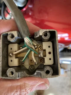
I had problems with starting and intermittent misfiring on my '73 Commando 850 when I first got it end of last season. I bypassed the kill switch and ran a wire directly from my Boyer black box to my key switch, and I am fairly confident this sorted the issues. However, I really would like to renew this switch and get rid of my bypass. My question is do the internals of my kill switch look complete or am I missing something?

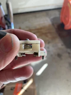
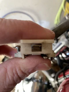
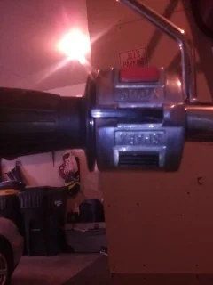
My switch is on the left handlebar and has a horn push button (bottom when mounted on bike), a kill push button (top red button), and the turn indicators as the paddle switch in the middle. Picture Switch 2 shows the horn which is normally open. There are two clean pancake-like contacts. Picture Switch 3 shows the other side where, as I understand it, the kill switch is normally closed, and depressing the kill button opens the circuit and effectively cuts out the ignition. Is it supposed to have some sort of contact points like the horn does? or is it just these two metal bits pressed together? I wonder if I just need to clean up the two metal bits and perhaps use some pliers to press and bend them together, or if I need to solder something in place to make sure the switch stays closed until the button is pressed.

Thanks
 

Attachments

  • Renewing Kill Switch
    Switch 1.jpg
    295 KB · Views: 198
  • Renewing Kill Switch
    Switch 2.jpg
    193.2 KB · Views: 125
  • Renewing Kill Switch
    Switch 3.jpg
    209.6 KB · Views: 124
  • Renewing Kill Switch
    Switch External.jpg
    177.7 KB · Views: 115
My switch is on the left handlebar and has a horn push button (bottom when mounted on bike), a kill push button (top red button), and the turn indicators as the paddle switch in the middle.

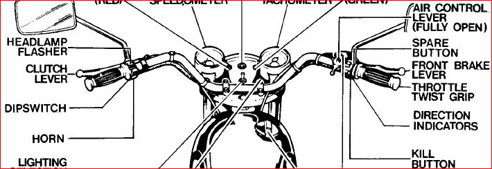
From '72-on that switch cluster with the kill button, 3-position direction indicator paddle switch and spare button would be on the right-hand side. The left-hand cluster should be the headlamp flash button (top), the two-position paddle operates the headlamp dip (high/low) switch and horn (bottom button) so the kill button and horn button are not in the same switch cluster.
Renewing Kill Switch

Picture Switch 2 shows the horn which is normally open.

That's the kill switch (white/yellow wire) so should be normally closed. The horn switch/wire would be purple/black and in the other cluster.

Picture Switch 3 shows the other side where, as I understand it, the kill switch is normally closed, and depressing the kill button opens the circuit and effectively cuts out the ignition. Is it supposed to have some sort of contact points like the horn does?

No, because it's not the kill switch, it is the spare button that has no wires or terminals. Correction white/red wire.
 
Last edited:
Well, I suppose then my bike has been modified or rewired at some point. What I can confidently describe is what is currently on my bike. As it sits, the left side has kill switch , turn indicator paddle, and horn; this is not theoretical as each button/paddle does what I just described. Right side has the paddle which flips between high and low, and a button that flashes the lights, and one button that does nothing, which I thought was for the later electric starts. But these switches are ambidextrous, no? So up and down on the left side is down and up on the right, if so desired by a previous owner...

Anyway, all the pictures I provided are from my left handlebar cluster, and the right side of picture Switch 1 is shown in profile in picture Switch 3, which appears to be normally closed and opens when pressed down by the red kill button (which I know works as the kill switch button). I think I am going to just sand and press the bits together with a pliers, but I am worried that the connection is not robust enough or missing something to stay closed with all the vibrations it will experience, hence my question.
 
Yes, you are on the right track. The power runs through the kill switch, so closed is run, push to open, kill the power.
Just a note and not a big deal but your bike has been modified as the Sparx cluster is aftermarket.
Someone has modified to their liking or not knowingly changed it.
 
Well, I suppose then my bike has been modified or rewired at some point. What I can confidently describe is what is currently on my bike. As it sits, the left side has kill switch , turn indicator paddle, and horn; this is not theoretical as each button/paddle does what I just described.

Correction: Text deleted.
Right side has the paddle which flips between high and low, and a button that flashes the lights, and one button that does nothing,

That's a left-hand cluster (see the previous diagram). The (upper?) "button that does nothing" should, therefore, be for the horn.


The switch clusters have been swapped over to the '1971' configuration below, where the upper left is the kill button, and the lower left button is the 'spare' (white/red wire?) nevertheless, the kill and horn push buttons are still not in the same cluster.
Renewing Kill Switch

which I thought was for the later electric starts.

The 850 Mk3 electric start model had completely different switch clusters although the spare button would have been used for the electric start as it was the factory's intention to fit an electric starter in 1971, however, that didn't happen.

Just a note and not a big deal but your bike has been modified as the Sparx cluster is aftermarket.

Although Sparx, the wiring colour codes and switch operation for the left and right-hand clusters are the same as the original Lucas.
 
Last edited:
My '74 MKII 850 had the switch cluster arranged as the Rider's guide book and LAB describe. But with this setup your right hand is very busying trying to manage throttle, brake and any needed turn signal on/off operations. Plus it is not standard with other modern bikes so another potential confusion.

So I did exactly what your bike has, swapped the cluster assemblies left for right. This flips them top/bottom but it all works great. Kill is at left top, horn connections are moved to unused left bottom button.

As for kill switch (my motorcycle training class instructor told me they are now supposed to be called shut off switches, to protect the fragile amoung us!!) I have run a bit of 220 wet/dry between the contacts for good preventative measure. I seem to recall there were "pucks" on the metal strips as actual contacts. While in there, carefully check the wiring as I had one or two being pinched between circuit board and metal casing, to point of insulation badly shredded and indanger of shorting.
I suppose I didn't think of it but that does make sense having the turn indicators on the left, less-busy hand, but I suppose you can get used to anything.

Your last paragraph is precisely what I am worried about. My normally open horn switch has the two pucks as you call them, but the normally closed kill which was intermittently breaking contact does not have anything like that. I thought perhaps they fell out or burnt up or I don't know what. Even with sanding and cleaning, it seems like you would want something more solid to make sure contact remains between these two metal strips.

With the Boyer, it seems to spark every time it turns on. So I think a millisecond of broken contact on my kill switch was causing the horrible misfiring.
 
My normally open horn switch has the two pucks as you call them, but the normally closed kill which was intermittently breaking contact does not have anything like that. I thought perhaps they fell out or burnt up or I don't know what. Even with sanding and cleaning, it seems like you would want something more solid to make sure contact remains between these two metal strips.

If the kill contacts look like the pictures in this thread then they're probably normal but in need of a cleanup.
 
If the kill contacts look like the pictures in this thread then they're probably normal but in need of a cleanup.
Brilliant, thank you. Looks like there is nothing missing, just needs to be cleaned.
 
Ok, things are clearer now (clusters are swapped) and the spare button (white/red) has been repurposed to operate the horn so for future reference, the white/red from the switch cluster spare button should connect to the purple/black (horn wire) probably at the main electrical junction point below the fuel tank.
 
Ok, things are clearer now (clusters are swapped) and the spare button (white/red) has been repurposed to operate the horn so for future reference, the white/red from the switch cluster spare button should connect to the purple/black (horn wire) probably at the main electrical junction point below the fuel tank.
This is what I have done on my setup. Works very well for me.
 
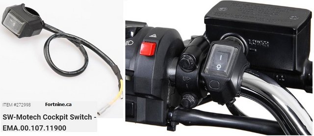
Over the years I got tired of having to fiddle with the kill switch losing contact and wired in a separate weatherproof switch.
Photos from Fortnine.ca
Renewing Kill Switch
 
Last edited:
Back
Top