Knocking / rattling inside primary drive case + backfire

Ok, slight leg pulling there.

Real answer with the current engine is: on the track I change up at 7k, which inevitably means sometimes being over that. On the road I tend to change up at 6 and a bit.

With the previous engine (stock crank and cases) I generally wouldn’t go much over 6 and a bit.
 
Interesting - you're describing pretty much where I started at.
When you get your new inner, or repair your old one, I would start with a clearance of 10 thou (3 places as per Norman White et al) and spray painted rotor (to show where any rubbing has occurred).
If there is evidence of rubbing after that then follow Nigel's route and machine the rotor.
My guess is a properly set up stator (well clamped) at 10 thou should be adequate.
Cheers
 
I would point out that in post 211 your rotor shows clear signs of rubbing. Why this is, of course, we have no idea.
You're right there.
But the next photo (had not seen before) appears to show only the outer 1/4 of the rotor has actually been engaging the shaft.
Maybe worn/dodgy ID on the inner half of the rotor?
(tried to copy here but "the system" says the photo is too large)
 
When you get your new inner, or repair your old one, I would start with a clearance of 10 thou (3 places as per Norman White et al) and spray painted rotor (to show where any rubbing has occurred).
If there is evidence of rubbing after that then follow Nigel's route and machine the rotor.
My guess is a properly set up stator (well clamped) at 10 thou should be adequate.
Cheers
For clarity, ‘my route’ wasn’t a suggestion or recommendation for others. It was merely an explanation of my route.
 
Thats only half of the test Rob… Now you just have to dismantle it to see if it has rubbed !
Yeah...
I tend to not go hunting for problems that have no signs of being there.
If it was rubbing I think there would be fine, magnetic particles (probably sticking to the stator plates).
Can't see any evidence of that (or any other symptoms) so I'll let sleeping dogs lie.
Cheers
 
I think that there is one factor that gets forgotten when trying to get rotor clearance. It is critical the the stator is mounted perpendicular to the crankshaft. There may be clearance at the front, but in the same position but behind there may be none, and the reverse on the opposite side of the stator. 10 or so thou can easily be lost if for example the centre stud is not shimmed properly, the stator spacers are not exactly the same height or the inner cover has suffered somehow. Perhaps the best way to determine this (after the crank has been proved true) is to mount the stator on the rotor shim it, then push it home and see if all three studs seat properly before being fastened.
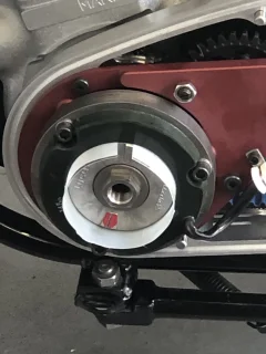
 
I think that there is one factor that gets forgotten when trying to get rotor clearance. It is critical the the stator is mounted perpendicular to the crankshaft. There may be clearance at the front, but in the same position but behind there may be none, and the reverse on the opposite side of the stator. 10 or so thou can easily be lost if for example the centre stud is not shimmed properly, the stator spacers are not exactly the same height or the inner cover has suffered somehow. Perhaps the best way to determine this (after the crank has been proved true) is to mount the stator on the rotor shim it, then push it home and see if all three studs seat properly before being fastened.
S’wot I do with the milk carton material…

Knocking / rattling inside primary drive case + backfire
 
Ok, slight leg pulling there.

Real answer with the current engine is: on the track I change up at 7k, which inevitably means sometimes being over that. On the road I tend to change up at 6 and a bit.

With the previous engine (stock crank and cases) I generally wouldn’t go much over 6 and a bit.
"6 and a bit" = 7k
 
Wow, lots on stators. Don't want to argue, just providing my experience.

On unit construction bikes, if I have trouble getting .008", I change/fix whatever is wrong. I've never had a stator/rotor rub except when a main bearing went - can be either side.

Except Norton I say away from non-unit construction bikes - just not my interest area.

For Norton I work to get .010 at the tightest spot. There are so many things flexing in a Norton that I like a little insurance. When I have trouble:
1) I start by measuring the stator spacers. I've found them to be three different lengths - up to about .005" between the longest and shortest. Moving them around sometimes resolves the issue. A way to tell this is a problem without taking anything apart is: find the smallest feeler gauge that will go all the way in at the tightest spot and then the largest that will go only part way in - if different, the stator is cocked.
2) I check the inside of the stator. In some cases, the encapsulation is extending inward past the metal. If I had the means to do it. I would use a mill or lathe to fix that and also take off a little. I like that better than reducing the rotor, especially if the rotor is reduced with high-speed steel inserts. Rubbing steel with steel and creating localized heat on magnets are both known to be bad for them. Nigle's efforts show it not to be a problem, so my concern is moot.
3) The stator should slip on the studs with minimal effort. If it doesn't, I use a tapered reamer to slightly open both sides of the stator holes but it does not touch most of the depth of the hole. If it still doesn't slip on, I change the studs. If it still doesn't, I try a different stator (I have a couple of original, but bad stators I use for this test). If that one doesn't slip on, I try to determine which stud is out of line and open the corresponding stator hole with a round file. If still no joy, I replace the inner primary.

You would think that the inner primary attached to the engine and to the cradle (only when the outer cover is on) could not flex in relation to the crank. I'm not so sure. I've found too many loose/improperly shimmed cradle to inner primary studs, loose engine to inner primary bolts, chains hitting the inner primary and so on.

Let's ignore chank flex. How about the built-in slop (C3) in the main bearings. On each revolution one piston is under great pressure downward and the other is not. There could easily be no runout manually turning the crank and quite a bit with the engine running. I can't find the C3 specification for the NJ306E.M1.C3 bearings most of us use but I'm guessing based on other bearings around 30 microns (.001"). So, one down and one up but the rotor is close to one (making my head hurt).

On any British bike other than Norton, I'm sure skimming the rotor doesn't do much to the output. I say this because the same rotor and stator work on Norton and they are not aligned so the magnet's effect on the stator are already different. Since it works for Nigel, it's probably OK there too. However, I get the impression that Nigel keeps the revs up (we all should). I bet if he installed an ammeter, still has the bridge rectifier and Zenor, turned on the lights, and road at 2500 rpm or less he would be running on battery. Even worse if running on a half-wave rectifier rather than a bridge. Yes, a "high output" stator would help, but what they really are is more turns of wire, so the magnets have more potential effect.
 
I believe the only reason you would require more than 10 thou is if your rotor, when mounted, is out of round.
A dial indicator will tell you this and where material, if any, has to be removed.
Increasing the gap will have a detrimental effect on the capacity of the alternator.
Increasing the gap will, in theory, decrease the Amp capacity of the alternator, but in practice, an increase of 20 thou, will be insignificant.

Assuming that the magnetic Flux decreases at the square of the distance from the stator (I am not sure if this is the physical law, but it is reasonable), and if the stock rotor diameter is 3 inches (just guessing), then the ampacity will decrease by (3/3.02)pwr2 = 0.987, or less than 2%!

Slick
 
Update: After making some enquires about repairing the inner primary case, and scouring the web to find a secondhand one (only one on the market, and it didn’t look great being from an accident damaged bike), I decided to buy new from AN.

The part arrived yesterday and I have to say, I’m really pleased with the quality of it. I’ve completed a test fit and everything is looking great - including stator alignment, which will need a little fettling but not much. I even managed to install the felt seal (see photo). wasn’t too bad!

Hopefully I’ll get some time tomorrow to finish the primary, then it’s on to electrics and backfiring issues.

Then checking everything else over… (trying not to think about what else could be wrong!)

26C3F0B8-1376-4171-ADAC-EAF71500A767.jpeg
 
Update: After making some enquires about repairing the inner primary case, and scouring the web to find a secondhand one (only one on the market, and it didn’t look great being from an accident damaged bike), I decided to buy new from AN.

The part arrived yesterday and I have to say, I’m really pleased with the quality of it. I’ve completed a test fit and everything is looking great - including stator alignment, which will need a little fettling but not much. I even managed to install the felt seal (see photo). wasn’t too bad!

Hopefully I’ll get some time tomorrow to finish the primary, then it’s on to electrics and backfiring issues.

Then checking everything else over… (trying not to think about what else could be wrong!)

View attachment 104019
*IF* that seal is all the way in, I want to know how you did it. I've tried everything anyone has said here and always have a major struggle. In the picture, it appears to me that you do not have it inserted all the way - they don't normally show anywhere near that much. Compare it to your other inner primary seal to see if I'm right.
 
I soaked the felt seal in oil for 5 minutes, then compressed it with my high pressure quick grip clamp (272kg of force) between two pieces of wood. I left it for about 30 minutes.

I removed the seal from the clamp and very quickly got it in before it started to expand. I nipped it in the middle to make it into a kind of plus shape first of all, and then fed it in all round.

When it was pretty much all in, I took a socket from my socket set that has a slightly smaller diameter than the clutch shaft, and used the socket to keep the seal in place while I worked in one little bit that wasn’t quite in.

I’ll take another picture with the seal on the shaft tomorrow. It seems to fit fine.
 
Update: After making some enquires about repairing the inner primary case, and scouring the web to find a secondhand one (only one on the market, and it didn’t look great being from an accident damaged bike), I decided to buy new from AN.

The part arrived yesterday and I have to say, I’m really pleased with the quality of it. I’ve completed a test fit and everything is looking great - including stator alignment, which will need a little fettling but not much. I even managed to install the felt seal (see photo). wasn’t too bad!

Hopefully I’ll get some time tomorrow to finish the primary, then it’s on to electrics and backfiring issues.

Then checking everything else over… (trying not to think about what else could be wrong!)

View attachment 104019
Good choice going new, you have removed a ton of variables that cudda bitten you in the arse !
 
So AN sells the inner primary with the round plates in place sans seal? I ruined one felt seal on my attempt so bought plates and several seals. Everything always works when you have backup parts!

Get that shim setup spot on. A 13/16" deep socket pushed through the seal and hard up against the gearbox guides the felt home. Mr. Hemmings recommends an additional felt seal over the gearbox sleeve before you do this for additional...sealing!
 
Back
Top