I went through this exercise about 2 months ago and have a couple of things to add.
First thing to say is that the clutch is now working fine and is much easier on older hands after 5 hours on the bike.
But I did have a few problems on the way.
The first problem was the pipe fitting into the slave cylinder leaked. It does not have a very big diameter so you cannot torque it up too hard but even when leaned on a bit it still leaked. Being in NZ I tried lots of fixes including making a tiny copper washer to seal the interface and refacing the surfaces as best I could but it still leaked.
Lots of e mails latter I had a new one from Colorado and it sealed no problem first try.
My next problem was getting it to bleed.
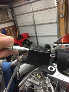
Reference step 5 above " Blow air into MC through little hole in one end, covering other little hole. 6. Actuator rod should move toward clutch stack."
I tried to do this for hours. Actually days but no way in a million years was that piston going to move back with the air pressure applied at the master cylinder as in the photo above. And yes I was using a big commercial shop sized air compressor.
So I took the slave piston out by blowing directly into the slave cylinder through a rubber seal attachment while it was on the bench to see what was going on.
The piston has the normal cup type seal for the hydraulic fluid but also an o ring to prevent contamination of the hydraulic fluid by the gearbox oil. This O ring was oversized and out of standard spec for the cylinder bore and piston size according to seal NZ distributors.
I checked this with Matt and he confirmed the O ring was purposely oversize and therefore had an extremely tight fit so there could be no contamination of the hydraulic fluid.
This presented two difficulties for me. Firstly the O ring and piston could not be reassembled in the normal way typical of any brake cylinder for example. It was necessary to make/ use a special tool to compress the o ring and then assemble the o ring and piston into the slave cylinder.
Secondly when the oversized ring was in place there was no way I could get the system to bleed by blowing air into the master cylinder. The friction was simply far too great to move the piston.
So after communicating with Matt and being informed of the purpose of the super tight O ring I replaced the tight O ring with the standard size spec and also machined a second back up ring groove in the piston. So now the piston has two standard fitting sized O rings plus the cup seal. I hope this two ring system with give the necessary protection from the gearbox oil to the hydraulic seal.
Having modified the piston I then went back to the standard bleed methodology blowing air into the small hole in the master cylinder and had the job done within an hour. No issues at all.
What I do not know is whether the oversized o ring and hence the problems I had are just me being hopeless or did I have a one off which wouldn't bleed in the normal way. Matt assured me he had bled similar units the same week i was trying without any issues at all. So the feeling I got was that I was wrong.
But I actually got two other guys to try when I couldn't get it to work.
One of them created this -
https://velocetteracing.wordpress.com/about-the-2018-iom-campaign/
That's a 1950 Velo DOHC works replica and last September it got a standing start 96 mph lap of the Manx GP. When I say created I mean make the patterns, pour the metal, machine the whole engine from castings etc etc etc. He didnt make the carb, the mag, the piston, valves and springs. But pretty much else he made. Including the frame. The carbon fibre tanks faring etc are ex Britten team guys including the guy who made most of the last frames, forks and swinging arms for the Brittens. He is just magical in what he can do.
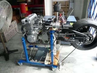
And the other guy created this.
That's a 1200 cc parallel twin with a third 180 opposed piston to counter vibration. Again designed, patterns made, castings, machined and on a dyno getting ignition and soon injection mapping. You can balance a glass of water on the head and it does not have a ripple on it. Amazing. This guys unusual in that he has an enginering degree but also 40 years as an engineering tradesman. Mostly as a pattern maker. So he can do the calculus and run the lath and milling machine. In his early days he was a mechanic on world superbikes.
Why am I saying all this? Basically to show it wasn't just me being an idiot. These guys are pretty good with bikes and they couldn't get it to work either.
But after modifying the piston as described above it all works fine.
Maybe it doesn't like bleeding upside down in the southern hemisphere. ;-)
I would be really interested in other peoples experience. Especially in the past 6 months which is the time period mine was supplied.