Crankcase bolt locations

mdt-son

VIP MEMBER
Joined
Jan 19, 2012
Messages
2,099
Country flag
Gents,

I want to go all the way with four sets of Commando crankcases, by preparing 10 mm fit bolts in lieu of the 3/8" bolts. There will be 5 x 10mm bolts similar to the Mk3.
To accomplish this, we will need to drill and ream each of the crankcase halves using a hardened boring plate.

Now, what I am looking for is a drawing which shows the theoretical location of the mounting bolts, either a copy of a factory drawing, or a drawing of CMM measurements recorded by a company or an individual. No worries, this is for my own use only.

If any of you possess such a drawing or sketch, I am happy to pay a fee for the right to use it for my own projects.

Regards,

Knut
 
Last edited:
Take a crankcase half, mount on a DRO equipped vertical mill and map out the hole positions.

I use TouchDRO which allows you to save hole positions, reload and then set any 2 holes before final clamping the case to table.
 
Take a crankcase half, mount on a DRO equipped vertical mill and map out the hole positions.
Thanks for the suggestion, Kommando. I would, if I owned a vertical mill! Still, the readings are as-is (i.e., as built plus wear). Finding the blue-printed bolt locations this way will be difficult, if not impossible.
Breaking this task down to smaller tasks, would NV use a datum point other than the crankshaft rotation center? I guess not. Finding the center on a finished crankcase requires a CMM, I think.
Unless someone performed this exercise before and is willing to share, we have to measure across the ridge running along part of the inner cavity, and determine location of the center by cross-referencing.
The result should be highly accurate. Hopefully, blue-print bolt locations relate to this center in or very near even numbers in (X, Y), giving us the confidence the (rounded) results are as per design intent.

- Knut
Hmm, if the main bearing holes were line bored, then the 2 halves would be bolted up first, meaning that the bolt holes would be done first. I wonder how they did this? I seem to recall that at Toyota, they clamped the rough casting down, machined 2 flat surfaces on the sides to give a X & Y reference and proceeded from there. You have to start somewhere, so perhaps Norton did the outer faces of the 2 halves, turned them over to use the machined face as a reference plane, did a rough alignment on the Z rotational axis and drilled the bolt holes?
There's some knowledgable machinists here, perhaps they could chime in?
 
Steve, thanks for your thoughts. Bearing holes can't be line bored because bearing seats are internal, making line boring impossible. The case halves were machined separately but in succession. Bearing seats were machined in the same go as the case flanges, the aforementioned ridge, and the two dowel positions which locate the case halves to another. Upon finished machining and joining of case halves, they were sent to the Tool Room for checking of critical dimensions. Upon approval, each case half was stamped. At AMC, QA stamping is seen inside the cases. With NV, the stamping is outside.

- Knut
 
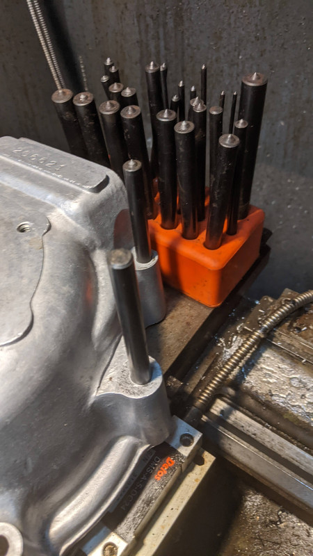
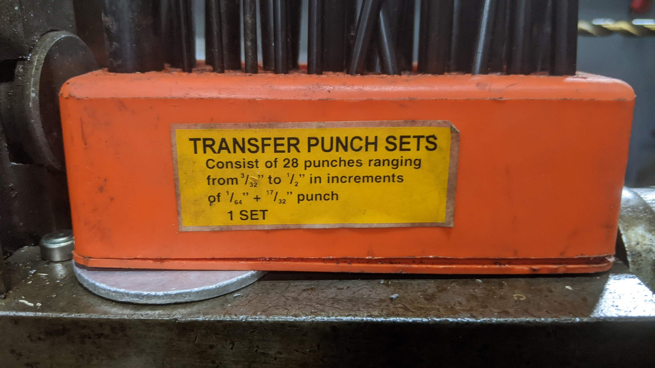
Transfer punches are old school but can be very accurate, trick is once you have the divots from the punch to start the drilling of the holes with a small drill so you are on the centre of the divot.

Crankcase bolt locations


Crankcase bolt locations


I have imperial and metric sets and pick the one that has a nice sliding fit with no rock, making custom ones up use silver steel so you can harden the tip.
 
Maybe NOC has access to this information?
If not people like Steve Maney must have.
NOC perhaps, but I am no longer a paying member. Steve has probably made the exercise described above, needed for his CNC fabrication of crankcases. He is spending his winters in Thailand and won't return until March.
I could ask AN, but little hope of receiving advice, they are very restrictive about sharing any kind of information. I may try Pete Lovell and Andy Molnar.

Transfer punches are old school but can be very accurate, trick is once you have the divots from the punch to start the drilling of the holes with a small drill so you are on the centre of the divot.
Certainly a low-cost procedure worth considering. Thank you so much for sharing!

- Knut
 
Last edited:
If you don't have a milling machine and DRO to do the locating, what are you using to do the work? Match the maintainable tolerance of how you're doing the work with how you're locating the holes.

If someone else is doing the reaming/threading, let them do the locating and piece holding on their machine, instead of teaching a journeyman machinist how to suck eggs.

If you're making a fixturing plate with drill bushings, the sequential transfer punch/drill/thread method should be adequate as long as you can drill the holes straight, which brings us back to who's doing the drilling to insure the holes' perpendicularity? There's got to be a milling machine in there somewhere to bring the tolerance up to your intended standard.

If you're doing it all by hand, just don't drink too many beers.
 
Last edited:
Hmm, if the main bearing holes were line bored, then the 2 halves would be bolted up first, meaning that the bolt holes would be done first. I wonder how they did this? I seem to recall that at Toyota, they clamped the rough casting down, machined 2 flat surfaces on the sides to give a X & Y reference and proceeded from there. You have to start somewhere, so perhaps Norton did the outer faces of the 2 halves, turned them over to use the machined face as a reference plane, did a rough alignment on the Z rotational axis and drilled the bolt holes?
There's some knowledgable machinists here, perhaps they could chime in?
Not sure if Knut is talking about Pre-MK3 cranks or MK3 cranks. This is for pre-MK3 cranks. I don't have much MK3 experience, but I think there are 6 bolts/studs in both Pre-MK3 and MK3 and the MK3 has another stud to replace the pin - the top two are still precision and are even called dowel studs.

Only the top two holes and the pin are precision. The top two holes are easily available when bolted up. The side two are available too but are a looser fit. The bottom two are likely located from the pin or after the other holes are drilled - they are looser like the two side holes. When people open up the top two holes so the bolts/studs fit "better" that are making a mistake!
 
Greg, this thread is about crancases, not cranks. See #7 and heading.

- Knut
Makes a lot more sense now. That's what you said to start but then #3 started me down the path of crankshaft and #8 perpetuated that.

IMHO, the crankcase holes are not critical as long as the bolts will fit through the two hollow dowels - they are the only precision holes and I've had to open one side or the other of the non-dowel holes from time to time because they were not well aligned. Since 3/8" is .375" and 8mm is .315" there is nothing to drill unless I'm still confused about what you want to do. If you want to open the 5/16" to 8mm just bolt the cases together, make sure the barrel surface is exactly in line and drill - of course, make sure there is enough "meat" to open up the holes. If you're talking about the cradle to engine bolts (probably are), bolt the cradle to the engine all except one bolt, make sure the barrel surfaces are exactly in line and drill, put in that bolt and move to another.
 
There's got to be a milling machine in there somewhere to bring the tolerance up to your intended standard.
Correct. Luckily, there are machine shops accepting such assignments. The engineering is performed by myself.

Good point using a milling machine and a probe instead of a CMM in locating the datum point and the hole centers. A CNC vertical drilling machine would do as well. However, once this is done, the stored data are good for one crankcase half only.
While occupying the milling/drilling station, it's more efficient to transfer strored data straight onto the fixture plate and use that as a guide for all subsequent drilling and reaming operations. We have at least 8 crankcase halves we want to drill and ream.
This can be executed with less fuss on a manually operated vertical drilling machine instead of CNC equipment. All we need is a table movable in X and Y directions.

- Knut
 
Makes a lot more sense now. That's what you said to start but then #3 started me down the path of crankshaft and #8 perpetuated that.

IMHO, the crankcase holes are not critical as long as the bolts will fit through the two hollow dowels - they are the only precision holes and I've had to open one side or the other of the non-dowel holes from time to time because they were not well aligned.
Dowels align the crankcase halves at two points only - everywhere else there are small differential movements along the crankcase joint. We see this at the bolt positions connecting crankcase to engine plates, and even the latter have suffered, as the holes show up elongated.
So here is our plan: We will use the fixture plate to drill all (4+1) 3/8" holes (which are about 9.8 mm in size) to 10 mm, ream them to tolerance, and fabricate oversize fitting bolts with a metric fine thread. Then we will reinforce the cradle's and front mount's plates. Using the fixture plate, we will drill and ream the mounts as well., ensuring improved load transfer.

Sounds like a lot of work for little gain? Perhaps, but we want to make sure the engine supports are firmly attached to the engine, with no possible movement between them, and no sagging of joints.

- Knut
 
Last edited:
Dowels align the crankcase halves at two points only - everywhere else there are small differential movements along the crankcase joint. We see this at the bolt positions connecting crankcase to engine plates, and even the latter have suffered, as the holes show up elongated.
So here is our plan: We will use the ficture plate to drill all (4+1) 3/8" holes (which are about 9.8 mm in size) to 10 mm, ream them to tolerance, and fabricate oversize fitting bolts with a metric fine thread. Then we will reinforce the cradle's and front mount's plates. Using the fixture plate, we will drill and ream the mounts as well., ensuring improved load transfer.

Sounds like a lot of work for little gain? Perhaps, but we want to make sure the engine supports are firmly attached to the engine, with no possible movement between them, and no sagging of joints.

- Knut
And I thought I was anal :) Just be sure the barrel surface remains true - the other things you mention are not machined surfaces related to the main bearings machined surfaces. Even with the dowels, they sometimes (often) need to be bumped into place slightly.

As others have mentioned, a fixture plate is easy if you have the exact size transfer punches and from the punch marks a sketch is easily made - just start with a set of crankcases in good order.

OK, you know what you're keeping me from - I'm out.
 
Dowels align the crankcase halves at two points only - everywhere else there are small differential movements along the crankcase joint. We see this at the bolt positions connecting crankcase to engine plates, and even the latter have suffered, as the holes show up elongated.
So here is our plan: We will use the fixture plate to drill all (4+1) 3/8" holes (which are about 9.8 mm in size) to 10 mm, ream them to tolerance, and fabricate oversize fitting bolts with a metric fine thread. Then we will reinforce the cradle's and front mount's plates. Using the fixture plate, we will drill and ream the mounts as well., ensuring improved load transfer.

Sounds like a lot of work for little gain? Perhaps, but we want to make sure the engine supports are firmly attached to the engine, with no possible movement between them, and no sagging of joints.

- Knut
Make four short expanding dowels from 1/2" steel bar ( the dowel part no more than an inch long) fit them in the top and bottom holes in the cases/cradle leaving the middle hole clear for reaming. Ream the hole till the cradle and case have cleaned up true. Make a high tensile steel fitted stud to fit the hole, making sure the plain section of the stud is long enough, to span the case and cradle, stopping just short of the cradle surfaces. Fit the stud and tighten in place. Remove bottom pair of dowels, ream and stud up. Same to top hole. Do the top hole last as that one has to be reamed from the drive side.
You will find 10mm reamers not big enough to clean up the holes, (wear, inconsistences in manufacture etc) compel one to ream slightly bigger to get a clean true hole.
Doing this to the front mount is a complete waste of time and effort in a Commando, the front mount has a huge rubber bobbin in it. The load transfer is all done between the engine and g/box cradle.
 
Last edited:
Make four short expanding dowels from 1/2" steel bar ( the dowel part no more than an inch long) fit them in the top and bottom holes in the cases/cradle leaving the middle hole clear for reaming. Ream the hole till the cradle and case have cleaned up true. Make a high tensile steel fitted stud to fit the hole, making sure the plain section of the stud is long enough, to span the case and cradle, stopping just short of the cradle surfaces. Fit the stud and tighten in place. Remove bottom pair of dowels, ream and stud up. Same to top hole. Do the top hole last as that one has to be reamed from the drive side.
You will find 10mm reamers not big enough to clean up the holes, (wear, inconsistences in manufacture etc) compel one to ream slightly bigger to get a clean true hole.
In-situ reaming is a possibility for the cradle/crankcase joints. Thank you for pointing out the possibility of a 10 mm reamer not being big enough. We use a 10-11 mm reamer. I will check my Mk3 crankcases - it's the one with most miles on it. My recently acquired cases off a '72 750 Combat is looking prestine and all bores are 9.7 -- 9.8 mm.
Doing this to the front mount is a complete waste of time and effort in a Commando, the front mount has a huge rubber bobbin in it. The load transfer is all done between the engine and g/box cradle.
You are joking, aren't you? If you really think load transfer takes place through the crankcase/cradle joints only, why don't you remove the front mount and see what happens? ;-)
What's the rubber bobbin got to do with it? There is one in the cradle as well, both are fully capable of transmitting loads. The spring and damper effect in the Isolastics doesn't mean static and dynamic loads aren't transmitted through the bolted joints at the crankcase!

- Knut
 
Last edited:
In-situ reaming is a possibility for the cradle/crankcase joints. Thank you for pointing out the possibility of a 10 mm reamer not being big enough. We use a 10-11 mm reamer. I will check my Mk3 crankcases - it's the one with most miles on it. My recently acquired cases off a '72 750 Combat is looking prestine and all bores are 9.7 -- 9.8 mm.

You are joking, aren't you? If you really think load transfer takes place through the crankcase/cradle joints only, why don't you remove the front mount and see what happens? ;-)
What's the rubber bobbin got to do with it? There is one in the cradle as well, both are fully capable of transmitting loads. The spring and damper effect in the Isolastics doesn't mean static and dynamic loads aren't transmitted through the bolted joints at the crankcase!

- Knut
Look at your crankcases. Which holes show where shuffling/wear has taken place? It is the three holes at the back that hold the crankcase to the g/box cradle. All the crankcases i have inspected show wear in this area. Now look closely at the front mount area, these two bolts never exhibit this wear, quite often the top bolt is seized in place!
It is the engine jiggling around in the g/box cradle (heavy engine attached to a heavy g/box and cradle) throw in the mix that all the drive loads from the engine go though these three bolts that cause all the problems. The front mount has a very easy life compared to the cradle. (it is only two small pieces of 3mm steel plate welded to a large steel tube) Ergo, using fitted bolts at the front is a waste of time and effort.
 
Back
Top