Broken Main Bearings (Outer Race)

Hey all...
Quick update to answer questions and give thanks to all for their input and suggestions.

Concours was correct in hís diagnosis and eagle eyed observation that the crankshaft boss has been contacting the outer race, and that has caused the failure of the outer mains race.

However, I don't believe it was caused by faulty manufacture of either crank or cases - it was by an assembly setup error by me when adapting my one piece RoDy Atlas style crank into the SBR billet cases (the alternator rotor key location is the only diff between Atlas & Commando racing cranks and Greg at RoDy had a ready to go Atlas style crank on the shelf when I needed one)

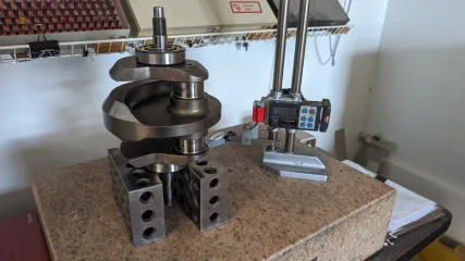
I reassembled the crank and cases with the still cracked mains to check that there was end float... And indeed there was - 0.015" - so preload wasn't cause.

SBR cases are machined for a Mk 3 850 crankshaft, which, I believe, is 3mm wider between the main bearings locations than the pre Mk3 models. To run a pre Mk3 crank in Mk3 cases you obviously have to add 3mm to the take up this additional clearance.

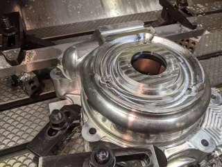
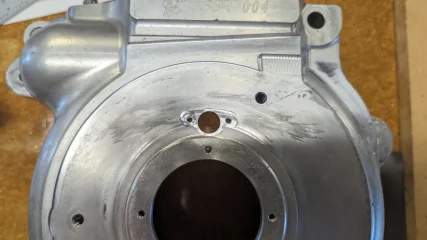
My problem was caused by the the manner I chose of shimming up this additional clearance. I chose to add a 1.5mm shim BEHIND each main bearing outer race rather than on the crank itself behind the lipped inner race. Placing the shims behind the mains outers has the effect of moving them out of their bores in the crankcase - you can see this protrusion clearly in the photos of the crankcase and fitted bearings.

My additional error was not considering / realising / checking that the crank wasn't contacting the protruding outer races. I simply assumed that the end float I was measuring was between the inner race and the outer race. Assumption is The Mother..

As the crank had plenty of end float, the cracking was caused by the crank being driven to left or right against the mains outers under load or deceleration.

I have new mains to hand now, and am considering splitting the shimming to both locations - some on the crank, some behind the mains outers. And I will check for clearance tween crank and mains outers..

I'll report back.. 👍

Thanks again all....
 
Last edited:
Behind the mains outer race, in the crank case.. This location was the cause. Just posted a longer update Re this..
Thanks.. 👍
And that’s why I asked the question. Your root cause analysis makes perfect sense to me.

As to re-assembly, when putting thin shims in place Comnoz recommends putting them behind the outer as you did, because he has seen crank mounted ones get spit out due to crank flex.

IMHO, given the thicknesses you’re talking about, this won’t happen.

So, to create a situation as close to design as possible, I’d fit the spacers on the crank. That will also have the added benefit of ensuring that the bearing outers sit fully home in the cases.

But my next question is: are you sure that the timing and drive side shafts protrude adequately to ensure everything fits as it should ?
Thanks for your comments..

Yeah, I agree that the thicker shims behind the inner race should be durable enough. I know Jim has SBR cases also - I know he's running a stroker custom crank but will check with him on how he shimmed also..

Re "protrusions".
Yes, all checked and OK. We had to do a lot of work to make the SBR race cases mate up with the stock pre Mk 3 primary - locating the D/S crank seal in the correct position was tricky, but we got it done.. See the attached pics from when we were modifying the SBR D/S case..

On another matter.. Jim has just declared that my big valve FA Gen 1 head is a piece of scrap now - he said it was machining like marshmallow, way too soft. Initially he thought I' may have overheated and annealed it, but as I have had a cyl temp gauge fitted since fitting the FA head, I can confidently state that it's never been over 405F, 99% of it's life running around the 325F mark. He's seen and has other "soft" FA heads at his shop. They were apparently cast from the wrong material..
Ouch. Expensive lesson.
 

Attachments

  • Broken Main Bearings (Outer Race)
    image (1).jpg
    394.5 KB · Views: 140
  • Broken Main Bearings (Outer Race)
    Screenshot_20230826-135019.png
    603.3 KB · Views: 134
Thanks for your comments..

Yeah, I agree that the thicker shims behind the inner race should be durable enough. I know Jim has SBR cases also - I know he's running a stroker custom crank but will check with him on how he shimmed also..

Re "protrusions".
Yes, all checked and OK. We had to do a lot of work to make the SBR race cases mate up with the stock pre Mk 3 primary - locating the D/S crank seal in the correct position was tricky, but we got it done.. See the attached pics from when we were modifying the SBR D/S case..

On another matter.. Jim has just declared that my big valve FA Gen 1 head is a piece of scrap now - he said it was machining like marshmallow, way too soft. Initially he thought I' may have overheated and annealed it, but as I have had a cyl temp gauge fitted since fitting the FA head, I can confidently state that it's never been over 405F, 99% of it's life running around the 325F mark. He's seen and has other "soft" FA heads at his shop. They were apparently cast from the wrong material..
Ouch. Expensive lesson.
Suggest that if you put spacers on the crank behind the inner race you keep the OD below that of the inner race lip. I also do not agree that the outer race interfering with the crank was caused solely by putting your spacers behind the outer race. The outer race is prevented from going past the lip on the inner race (required to facilitate contact with the crank) by the rollers rubbing against their shoulders on the inner and outer races. Perhaps the rollers on your mains were slightly short - unlikely, I know, but not beyond the bounds of possibility. You should check to see just how much (or not) the inner race sits inside the outer when the rollers are up against their shoulders. The machined shoulder on the crank mainshaft will take care of a couple of thou here so long as it is no bigger than the outer race inner diameter, as mentioned earlier. Also, putting the spacers in the crankcase instead of on the crankshaft actually provides better crankshaft support
 
Suggest that if you put spacers on the crank behind the inner race you keep the OD below that of the inner race lip. I also do not agree that the outer race interfering with the crank was caused solely by putting your spacers behind the outer race. The outer race is prevented from going past the lip on the inner race (required to facilitate contact with the crank) by the rollers rubbing against their shoulders on the inner and outer races. Perhaps the rollers on your mains were slightly short - unlikely, I know, but not beyond the bounds of possibility. You should check to see just how much (or not) the inner race sits inside the outer when the rollers are up against their shoulders. The machined shoulder on the crank mainshaft will take care of a couple of thou here so long as it is no bigger than the outer race inner diameter, as mentioned earlier. Also, putting the spacers in the crankcase instead of on the crankshaft actually provides better crankshaft support


As previously explained.

Broken Main Bearings (Outer Race)
 
As previously explained.

View attachment 109444
Yep, I totally, completely, absolutely, 100% understand how the lipped main bearing works.
Unless you are familiar with just how much spacing is required to fit a pre MK3 style crank into SBR cases, and that as a result the mains outer shell protrudes from it's hiis
Suggest that if you put spacers on the crank behind the inner race you keep the OD below that of the inner race lip. I also do not agree that the outer race interfering with the crank was caused solely by putting your spacers behind the outer race. The outer race is prevented from going past the lip on the inner race (required to facilitate contact with the crank) by the rollers rubbing against their shoulders on the inner and outer races. Perhaps the rollers on your mains were slightly short - unlikely, I know, but not beyond the bounds of possibility. You should check to see just how much (or not) the inner race sits inside the outer when the rollers are up against their shoulders. The machined shoulder on the crank mainshaft will take care of a couple of thou here so long as it is no bigger than the outer race inner diameter, as mentioned earlier. Also, putting the spacers in the crankcase instead of on the crankshaft actually provides better crankshaft support
Thanks for your input. 👍

The bearings are FAG C3 supplied by AN, so I'm "pretty" sure there's no issue with bearing peculiarities.

I'm 99.999% sure that the spacing issues are totally the result of adapting a custom made one piece Pre MK3 width crank into custom made SBR cases which require either the 3mm wider Mk3 crank, or that 3mm clearance shimmed in some fashion. Because I fitted shims behind bearing outer (in the case), each outer now protrudes from it's bore by approx 1mm. You can see this in the uploaded photos This outer race protrusion doesn't /can't happen in a stock crankcase. With a stock crankcase the main bearing outer race sits either flush with or below the crankcase.

As Concours identified , the crank cheek boss is the contact tween crank and the protruding outer bearing shell. I may have to grind the crank shoulder boss down to prevent this occurring..

I'll report back..

Thanks again for your input.
 

Attachments

  • Broken Main Bearings (Outer Race)
    PXL_20230811_225946192~2.jpg
    312.4 KB · Views: 108
Update / Resolution..(minor edit Sept 4, 9pm)

Thanks all for your input and suggestions. I've resolved the issue and have the bottom end assembled now.

After a discussion with Jim Comstock, we decided it was best to leave the shims behind the bearing outers, in the crankcase.
We chucked the crank up in the lathe and turned 20 thou from both timing and drive side bosses on the crank - so reducing the width of the crank between these two points by 40 thou total.
See the before and after photos..

We then fitted the new inner races to the crank., but before fitting the inner races we ground a small chamfer on the top edge of back of the inner race to facilitate easier removal with a bearing puller in the future. It makes it so much easier..

One thing we noticed on assembly of the new inner races in the crank was that despite the new bearings being the same make / model of Indian made FAG NJ306E C3 as those we were removing, the inner radius at the rear of the inner race where it butts up against the crankshaft was different to the radius of the old inner races we were removing - we checked using radius gauges. Worth checking before you fit new mains, as if the inner race rests on the shaft radius rather than butting up against the cheek, it's going to be unstable and affect end float.

Before fitting the outer races to the cases we slipped the outers on the inners, then accurately measured the overall length of the crank from bearing to bearing using a digital height gauge on a granite measuring bed. Then we fitted the shims and the bearings outer races to the crankcases, and then repeated the same measurement on the cases using the digital height gauge. From these measurements we could predict the crank end float without needing to assemble, disassemble and adjust, shims then repeat.
The height gauge measurements predicted an end float of 20 thou, which we called good. Then crank and cases were assembled..

Sludge Trap Shenanigans.
My one piece Ro-Dy crank has a simple 3/8" inch drilling to act as a sludge trap - holding MUCH less "sludge" than the stock Norton crank can accommodate, so more frequent disassembly and cleaning would be necessary. Prior to assembly I of course inspected and cleaned the trap. On my trip to from San Jose, CA to Ushuaia via Central America then back to Lima Peru, I covered a total distance of around 25,000 miles, much of it rocky, dusty and sandy. The oil (Motul 7100 20w50 was the easiest to find in Central and South) got dirty quickly, but was changed frequently.. Heck it's a Norton...mine was using a 600ml / 1 pint per 600 miles / 1000 km approx. So after 3000 miles it's had an additional 5 pints /3 litres of fresh clean oil added.
Upon removal of the oil gallery access set screws, I found the 3/8" gallery was approx 65-70% full - more than I was comfortable with. Perhaps the piston failure in Lima was a blessing and saved the crank?


So with my Ro-Dy crank, and my intended round-the-world usage with a potential 25,000 miles per year, the thought occurred that the engine would need removal and cases split and crank removed, sludge trap cleaned...EVERY.SINGLE.YEAR

My friend Rick and I scratched our heads a bit and came up with the idea that if an access bung / plate was added to the right spot on the crankcase, it could be removed and the sludge trap inspected and cleaned by flushing and with a carefully wielded augur (extended drill bit) with the engine in place. The plan would be to remove the sludge trap access plate, then remove the sludge trap set screw, screw in a hollow adaptor into the sludge trap access hole, then remove timing cover, fit a hose to the end of the crank and gently pump solvent (actually, we found simple petrol works best as a sludge liquifier after testing a few solvents) through the crank and out of the hollow adapter to exit the crankcase on the drive side, while gently rotating the long drill "augur".
I've uploaded some images of the new sludge trap access port, the access port cover, and the cleaning hollow adaptor tube.
I'm pretty confident that if I check and clean the sludge trap once a year I'll be able to put off complete engine teardowns well beyond 12 monthly / every 25,000 miles.

Other things we did along the way...

Fitted stock length (heavy) Carillo rods so that I can use "heavy" stock pistons (skirts anti-friction coated by Line2Line) running at 0.002" clearance (to coating) in Andy Molnar's / TGA nikasil ceramic coated aluminium (there's an "i" in it..

) barrels. Back to trusted heavy and reliable for me - no more lightweight pistons for my a special application. I've tried 3 different piston lightweight suppliers, and more than one set from each - those I've tried simply can't take the load induced heatsoak at loaded "slogging" revs (3000-4000 rpm). When you're climbing relentlessly from 5000 ft to 17,000 ft asl in the Andes negotiating gravel, rocks, washboard, with deep sand and bulldust on the numerous hairpins threatening to wash the front wheel out, you find yourself gritting your teeth fixated on the barrel temp gauge relentlessly climbing toward the Oh Shit zone - 345F with lightweight pistons in my engine. At 345F, the lightweight piston has expanded by 8 thou, but the cast iron barrel has grown only 2 - 3 thou. At 345F the stock iron barrel says Come To Mama to the pistons..
At 4500+ rpm the Norton twin engine runs MUCH cooler - the barrel temp drops like a stone to 260 to 270F or lower at those rpms. But you can't get there in the above-mentioned Andean type conditions...unless you're Pol Tarres or Chris Birch...Well, I can't...

That's it for now..I'll post updates when I'm up and running again..
Thanks again all..👍
 

Attachments

  • Broken Main Bearings (Outer Race)
    PXL_20230829_193841533.jpg
    161.5 KB · Views: 99
  • Broken Main Bearings (Outer Race)
    PXL_20230829_191929682.jpg
    174.5 KB · Views: 88
  • Broken Main Bearings (Outer Race)
    PXL_20230829_231902361.jpg
    211.5 KB · Views: 85
  • Broken Main Bearings (Outer Race)
    PXL_20230831_211818316.jpg
    291.1 KB · Views: 86
  • Broken Main Bearings (Outer Race)
    PXL_20230831_211844222.MP.jpg
    212.2 KB · Views: 80
  • Broken Main Bearings (Outer Race)
    PXL_20230831_223540639.jpg
    145.3 KB · Views: 86
  • Broken Main Bearings (Outer Race)
    PXL_20230902_235323245.jpg
    201.1 KB · Views: 83
  • Broken Main Bearings (Outer Race)
    PXL_20230902_235248696.jpg
    224.8 KB · Views: 79
  • Broken Main Bearings (Outer Race)
    PXL_20230901_232500317.jpg
    266.6 KB · Views: 89
  • Broken Main Bearings (Outer Race)
    PXL_20230901_230058052.jpg
    220.6 KB · Views: 94
Last edited:
Fascinating thread, John. Looks like you have it pretty well sorted, so maybe the next adventures will work out a little better. I'll try to keep up with you on FB too, but spare some time for an update here on the forum once in a while, please, particularly the technical details.

Ken
 
Fascinating thread, John. Looks like you have it pretty well sorted, so maybe the next adventures will work out a little better. I'll try to keep up with you on FB too, but spare some time for an update here on the forum once in a while, please, particularly the technical details.

Ken
Yep, thanks Ken.. Will do.. 👍
 
For a while now I've been thinking that cruise speed of 70mph/3800 rpm in the hilly world in which I live is really too low.
Your comments on higher rpm lower temps pretty much have pushed me into ordering a box sprocket with one
less tooth than now.
 
Back
Top