marshg246
VIP MEMBER
- Joined
- Jul 12, 2015
- Messages
- 4,128
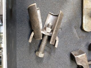
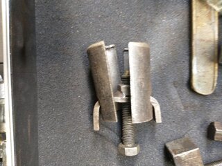
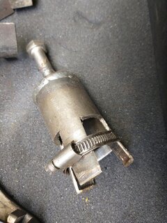
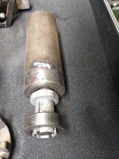
Buy a "perfectly restored" bike. Check it over - no 4th gear. Drain the gearbox - combination: ATF/Water/Grease and stinks. OK, outer cover a bear to get off - glued on with some sort of black substance. Easy enough to see that the shift quadrant is off one tooth. Try everything you can think of to get the inner cover off - no way. On the bench you could use a rubber hammer on the back, but not in the frame. Finally made the contraption in the picture. The wrench already had a hole at one end. Drilled and tapped for 3/8" UNF and used and old wrench to old the other end down. Used grease to hold a washer in place to protect the end of the main shaft while tightening. Had to tighten the bolt a LOT to get the cover to break free.
The inner cover was glued on with some sort of grey crap. All told, 3.5 hours to get it apart and get the gasket surfaces cleaned! Then a half hour to get all the ATF/Water/Grease cleaned up. Still have to put it back together.

The inner cover was glued on with some sort of grey crap. All told, 3.5 hours to get it apart and get the gasket surfaces cleaned! Then a half hour to get all the ATF/Water/Grease cleaned up. Still have to put it back together.