What is the best Alternator Rotor available today (2019)

Status
Not open for further replies.
Are those rotors balanced, even if so a recheck could never hurt.

I remember reading an article although can't recall the exact numbers where an ounce of out of balance out there on the end of the crank was (iirc) equivalent to 126 lbs at reline (4 cylinder bike)
Once that early style center comes loose all crank balancing goes wonky. Then bad stuff happens. Pre 1971 in my recollections.
 
the myth of welded centre is actually true

early rotors have a parallel centre tube cast in seperatley which is prone to break loose from the outer

later Lucas rotors have a spider arrangement cast in to hold magnets in place (this is not welded to the magnets ) these are dovetailed in to the spider by slotting them in prior to die casting

Wassell rotors and new Lucas rotors are made in this way so to remove magnets it requires a lot of cutting

Some time back i stripped a couple of rotors by cutting through them to check internal make up the Wassel / Lucas rotors are very well designed and will not come apart without considerable brute force
 
Once that early style center comes loose all crank balancing goes wonky. Then bad stuff happens. Pre 1971 in my recollections.

I was wondering about the modern rotors also, there looks to be no balance dimples of any sort.
 
I was wondering about the modern rotors also, there looks to be no balance dimples of any sort.

The NHT crankshaft is 19-22 lbs @ 52% balance
how much is crankshaft unbalanced?, compare to almost microscopic alternator rotor imbalance?
In physics... 6000rpm is molasses slow. Compare to 45,000rpm of drouin impeller
A pair of superblends are doing there job.
At this point I'm not loosing any sleep.:)
 
the myth of welded centre is actually true

early rotors have a parallel centre tube cast in seperatley which is prone to break loose from the outer

later Lucas rotors have a spider arrangement cast in to hold magnets in place (this is not welded to the magnets ) these are dovetailed in to the spider by slotting them in prior to die casting

Wassell rotors and new Lucas rotors are made in this way so to remove magnets it requires a lot of cutting

Some time back i stripped a couple of rotors by cutting through them to check internal make up the Wassel / Lucas rotors are very well designed and will not come apart without considerable brute force
the term welded is defined by a little known definition of "welded"; ..."to unite or reunite closely or intimately" Websters.

heres what Lucas says, just as you found out.

Hello Jim


The term welded centre refers to the internal makeup of the rotor


Original rotors produced in the 1960`s used a hexagonal shaped bar ( external ) for the centre which was internally bored to ¾” shaft size

the magnets seated on the flats of the hex and were then placed in to the die cast mould once the casting had formed around the magnets they were reliant on the soft casting material for positive location , they were very prone for breaking loose due to the reciprocating weight of the rotor

it is not uncommon to find early rotors with a loose centre


current production make up has changed to eliminate this issue


the centre core is in effect now a 1 piece spider with reverse dove tails to retain the tapered magnets , these are slotted in to the core prior to the pressure die casting process which then fully encapsulates the centre core and magnets in effect making it one piece construction , rotors are then CNC machined to internal / external tolerances


Regards
 
I believe that the most important issue when fitting new rotor or stator or both, is ensuring good rotor to stator clearance.

On my previous engine build, I ensured I had the requisite .010” clearance using the original rotor and a new stator. But upon disassembly I saw signs of rubbing and an unhappy stator.

So, on the latest rebuild, I had my machinist mate properly measure the ID of the new stator and OD of the new rotor. There was less than .010” clearance, and thats best case, ie without any minor misalignment when assembled.

I had him turn the rotor down to give .020” clearance all round. I then assembled it as shown below. The plastic ‘sleeve’ is to ensure even clearance as things are tightened up and (this should be obvious, but just to be clear) it’s then removed before being run.

It is not a trouble to remove 0.010 to the stator for the magnets ?

I have the same problem as you with rotor and stator LUCAS.
 
Last edited:
I’m not sure what your question actually is?

I had the rotor measured for concentricity, it was good.

I had the stator ID measured for roundness and concentricity with the 3 mounting holes, it was good.

I had the ID and OD measured, it was not good. It was less than .010” clearance. My previous one had rubbed even with a confirmed .010” clearance.

So I had the rotor turned down to give a .020” clearance all round (ie.040” difference).

So far, all seems well.
Hey if you are putting out the same A.C. power as before the reduction operation then we should all do this. Maybe send the rotor to D.D. for output testings or Lucas ? Patent your idea first.
 
I have been given three six volt stators and rotors (the smaller diameter ones) Two of these rotors have got worn center holes rendering them scrap although they seem to have quite good magnetism. My question is how thick is the wall in the center boss in these rotors? Is there enough metal to bore out and sleeve back to 3/4" with a new keyway?
 
Hey if you are putting out the same A.C. power as before the reduction operation then we should all do this. Maybe send the rotor to D.D. for output testings or Lucas ? Patent your idea first.

I have no idea what the output was before or after, I just know it works!

I can’t really Patent the idea seeing as Stan Shenton beat me to it by 50 years or so...!
 
if the Lucas rotors and stators are both concentric the problem lies with the stator mounting or main bearing fit

dont forget the stators are mounted to the commando chaincase which is seperate to the crank cases a few thou of miss alignment will reduce the air gap
there is also some movement on the stator mounting studs a + or - of 5 thou can be gained by levering stator on its studs when tightening nuts
and any play in the main bearing will also be accentuated at the crank end especially on over run
 
Don’t forget the OP is running a MK3, so there is more to consider.

As I have said already, I have found the clearance is even less on a new genuine Lucas rotor and stator, when compared to the original so it is important to be careful.
We have turned down the rotor in the lathe to provide an air gap we are comfortable with taking into consideration crank flex.

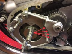
On the topic of the rotor running concentrically inside the stator with an even gap all round, because it’s a MK3 you cannot take the usual route and either ‘waist’ the mounting studs or ream the holes in the stator to give you the wiggle room you need.
The reason being, the cast aluminium outrigger plate holds the stator in place not just on the three mounting studs, so it doesn’t give you the same degree of room for manoeuvre.

The answer, I’m afraid is to gently remove some of the material on the outrigger with a dremel.
Incidentally, I have seen a tight spot in exactly the same place on our own MK3 and several people online who have posted pics of similar.
What is the best Alternator Rotor available today (2019)

We have reamed the holes in the stator - this allows us to move the stator over to the right and up a little.

It’s a good idea to use a cut up Coca-Cola drinks bottle wrapped around the rotor to ensure that clearance is right and stator is centred about the rotor.
 
We’ve machined down a couple of rotors now in the lathe - they machine very nicely.
Just need to keep the air compressor blowing the swarf away as it cuts.


I have found the new genuine Lucas rotor and stators to be made to a tighter tolerance than the old ones.
That would usually be a good thing, but in this case it made me uneasy given the possibility of crank flex, which is why we now machine them.

I’ve seen zero noticeable degradation in output/charging.


I have exactly the same problem on my 850 MK3 as you.
How much should the diameter of the rotor be reduced ? 0.010 ?
 
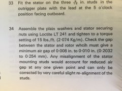
The Commando manual calls for a minimum air gap of 0.008 to 0.010 inches

What is the best Alternator Rotor available today (2019)

We have a plastic shim that we wrap around the rotor when we’re installing the stator.
The shim is 0.25mm which equates roughly to somewhere between the two imperial measurements in the factory manual.

With the brand new genuine Lucas rotor and stator, we couldn’t get the stator over the rotor with the shim strip in place.

When we measured the diameter of the rotor, it was a tad over 74.1mm
So on the lathe, we took the rotor down to 73.9mm

The shim strip slid in easily - and I was a lot happier there’d be no fouling.
 
If I found such a condition I'd want to know why the bore is worn, being loose would be my first guess. If that is the case than I would want to know if the crank pin it fits onto had suffered any damage. If you have already put those considerations to rest then the question, in my mind, would be, is there any difference, or is there a threshold, in the gauss numbers.

Dynodave comes to mind for such a question; certainly others may have some knowledge here; I do not. My gut tells me that new rotors may be created with equal gauss, and may all be made at the same factory, but I can't say for sure.

Best
got the new lucas rotor and it is tight on the crank, might have to hone it a little.
 
Here is a normal commando era rotor.
Put a rotor in a plastic container with NaOH/sodium hydroxide/lye/drain cleaner.
This is what you get!
Center hex carrier, load material cubes(to be magnetized), and the focusing armatures around the OD.
FA are laminations then with a peened steel dowel for retention of laminations as an assembly..
IMHO...If the center and load material were furnace brazed together could you possibly call it a welded center.
Cast molded in aluminum or some pot metal alloy?
1. Then machined on the OD.
2. Then magnetized.
3 Timing mark always directly above center of broached keyway, which is always magnetized as North.

What is the best Alternator Rotor available today (2019)


I did this well over 10 years ago!!!
 
Timing mark for a Commando is the one opposite the keyway.

Thanks for the reminder.
Out of about 15+ in my box only 5 were therefore commando. Most had dual marks, a few only above keyway(featherbed?) and one with no timing mark. The stamped lucas PN did not seem to make any difference to the timing mark/marks placement?
 
Thanks for the reminder.
Out of about 15+ in my box only 5 were therefore commando. Most had dual marks, a few only above keyway(featherbed?) and one with no timing mark. The stamped lucas PN did not seem to make any difference to the timing mark/marks placement?

I've only fondled Commando rotors - Lucas and others. All had dual marks and I know the correct one is across from the keyway. I've marked mine so I never make the oops mistake again.
 
Status
Not open for further replies.
Back
Top