Weird problem with the timing mark on my 850

Status
Not open for further replies.

N0rt0nelectr@

VIP MEMBER
Joined
Sep 15, 2014
Messages
1,154
Country flag
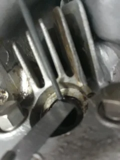
I expect this has been discussed before but I can't find the link. Late last year I had the sprag go out on my CNW starter. Matt as I said before was right on it and sent me a new one. The sprag was easy enough to install and I hadn't touched a thing timing wise. Then I decided to replace the oil pump with a new one I had sitting on my shelf. I replaced the seals and reset my timing per Pazon's instructions. I didn't touch the timing chain. Now it get interesting.
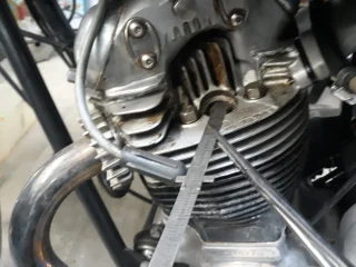
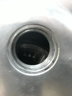
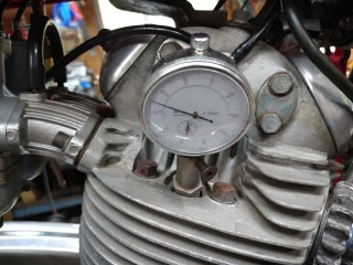
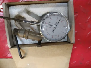
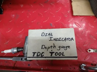
Before the timing mark was spot on. Now when I measure the advance on the piston it's no where close. If I set it up using the timing mark and checking that against the piston it is way off and runs terrible. I am sure I'm missing something simple but what it is. When setting it up with the piston at 5/16"BTDC it starts and runs just fine. Like I said it's weird.
Ideas, suggestions?
Thanks
John in Texas
 
maybe center of the altenator rotor is loose, could be the timing plate is bent sideways.
 
i know you're running a CNW starter, but recently, i sheared the woodruff key on my alton's sprag clutch/rotor assembly - timing mark shifted about 90° - boogered up the crankshaft end to boot. in a perfect world, a good design - real world, (IMHO) not so good. i was able to clean things up, and repair, and things seem OK, but if it happens again, i've got problems.
 
The rotor on mine had timing marks on both sides. I put in on backwards once and caught the mistake before starting.
 
I have a spare rotor and replaced it with no difference.
I expect it is something simple but in the 45 years of owning this bike I have never had such an issue before.
Time to stare digging and checking things again.
Thanks to all who have offered their insight.
 
The only way to know for sure is to check everything with a degree wheel. Much more accurate than a chiseled hash on a small circle (the rotor). You can also check to see if the cam timing's correct, or if it's a tooth off.
 
With my MK 111 the timing screw/bolt viewing port is on the R.H. side lower crankcase.
Could not find the manual's mark for T.D.C. no matter what I did .
So this was after new 40 over rebore / pistons .
Settled for a T.D.C. lockdown for the new Boyer MK 1V unit . Figured I could move the plate a bit should need be.
Fired up instantly and has run perfect for the past 3 years. Got lucky I guess.
We put a timing gun to her (revved up) up on a hoist a year ago with no readings. None.
That was through the primary viewing screw port for timing.
My technician said there was likely a problem with the rotor itself.
Since then I have disassembled the primary and re-assembled it with several new CNW components.
Rotor seems fine. Fired up first attempt . Ran fine.
This motor as purchased had suffered a catastrophic failure due to a P.O.S. anti-drain valve and threw the timing side rod. Regrind and weld up to the upper R.H. case where the rod hit. I did not rebuild the lower end only the barrels and head which were both handed over to competent machine shops in S.W. Ontario.
Lots of driving coming up this summer so leave sleeping dogs lie.
The MK3 plug on the engine's right side uses a factory tool , # 06-6473 , It located the timing mark . I checked mine and it does .

What do you mean by "No Reading" If you have an OEM rotor, I would think the timing mark is accurate.
 
Last edited:
Late yesterday I opened up the primary and rechecked the rotor and the woodruff key. All are where they are supposed to be. Sent Jim Comstock yesterday an email on this but as of now no reply. I will let you know what he says.
 
The MK3 plug on the engine's right side uses a factory tool , # 06-6473 , It located the timing mark . I checked mine and it does .

What do you mean by "No Reading" If you have an OEM rotor, I would think the timing mark is accurate.
Thanks . I will order in this special tool.
My technician was a bit baffled too and said maybe the rotor key had sheared off when the engine seized and the rebuilder simply put the rotor back on the shaft and tightened it down in any position. Seemed plausible but when I rebuilt the primary last winter the key was in it's slot and the O.E.M. rotor fitted over it properly. I'll view things there again when I open up the clutch to fit an extra steel plate to bring up the stack height .
 
With my MK 111 the timing screw/bolt viewing port is on the R.H. side lower crankcase.
Could not find the manual's mark for T.D.C. no matter what I did .

There isn't a TDC mark, only full advance.

Thanks . I will order in this special tool.

The tool isn't necessary as the timing slot (full advance) is easy to see and position in the viewing port.
Weird problem with the timing mark on my 850
 
Thanks . I will order in this special tool.
My technician was a bit baffled too and said maybe the rotor key had sheared off when the engine seized and the rebuilder simply put the rotor back on the shaft and tightened it down in any position. Seemed plausible but when I rebuilt the primary last winter the key was in it's slot and the O.E.M. rotor fitted over it properly. I'll view things there again when I open up the clutch to fit an extra steel plate to bring up the stack height .
Check the rotor nut for Torque, I re tighten mine after I installed the CNW e start twice, I did check it and noted how much father I re tightened it. An redid the nut after cleaning the threads and put a coat of new blue lock tite on to make it right.
 
FYI, the primary cover timing scale on a MKIII is screwed to the cover not riveted and can be moved on its slotted holes causing misadjustments.
 
I did a post called "Linear Piston Travel and Advance Degrees." The chart is below. It is compensated for the spark plug hole angle with the Green numbers. I have a dial indicator that screws into the spark plug hole. The tip is ground into a rounded ball which slides across the piston easily. I find TDC by turning the rear wheel in high gear until the dial indicator is at it's peak. This method allows you to find thirty one degrees or twenty and any in between without taking off the rotor or the primary cover. Just set the piston .362 inches (9.205mm) before top dead center and run around the other side to see if your mark is correct on the primary cover degree markings. I would try it several times to make sure the dial indicator is repeating accurately. If your degree marker is off a little then make a note of how much and keep a record of that so that you can always time that particular Norton accurately with the strobe.

31°= .320" (8.127mm) BTDC (Before Top Dead Center), 0.362” (9.205mm) (compensated for the 62° spark plug hole angle.)
30°= .300" (7.630mm) BTDC, .340” (8.642mm)
29°= .281" (7.147mm) BTDC, .319” (8.095mm)
28°= .263" (6.678mm) BTDC, .298” (7.564mm)
27°= .245" (6.224mm) BTDC, .278” (7.049mm)
26°= .228" (5.784mm) BTDC, .258” (6.551mm)
25°= .211" (5.359mm) BTDC, .239” (6.070mm)
24°= .195" (4.949mm) BTDC, .221” (5.605mm)
23°= .179" (4.554mm) BTDC, .203” (5.158mm)
22°= .164" (4.174mm) BTDC, .186” (4.728mm)
21°= .150" (3.810mm) BTDC, .170” (4.315mm)
20°= .136" (3.462mm) BTDC, .154” (3.921mm)

The figures in GREEN are corrected for the 62° angle of the spark plug hole. When the gauge measures 1 inch of travel the piston will have moved .8829" down so the gauge needs to read more than the actual piston travel to give you the actual piston travel. According to Jim Comstock the crank offset he has measured was only .5 to 1.0mm on 750 and 850 Commando engines which is not much. And, of course, if the piston is domed or dished the dial indicator will be hitting a different part of that dome or dish at the different distances from TDC as it moves across the piston because of the 62° angled spark plug hole.

(One small disclaimer: If you are running rods of any length other than stock then these numbers will not work for your engine. )
Boy, you sure have thought that out. I'm going to print that out and put it into my factory shop book.

Now, don't cringe. What I have done is clipped a 6" steel rule to the top fin so I always read at the same point. Took an old spoke held vertically in the plug hole and bump the rear wheel to TDC and then marked the spoke. Measure back up 5/16" for 28 degrees and put a second mark on the spoke. I say up because it will need to be BTDC. Then I bump the rear wheel backwards until I'm just past the second mark then forward to the top mark on the spoke. Comparing this to the mark on the rotor and degree mark I can see if I'm even close.
Yesterday I opened up the primary and checked to make sure the rotor was tight on the crank and that the woodruff key was where it needed to be. It was.
I rechecked and when I set the timing mark at 31 degrees it is way advanced. I will look to buy or build a piston stop and the type of dial indicator motorson described. Here are a few pictures of what I was trying to describe on how I was using a spoke to check the amount of advance on the piston. Yes it is low tech but it puts me in the ball park.
 

Attachments

  • Weird problem with the timing mark on my 850
    20210421_110224.jpg
    257.2 KB · Views: 155
  • Weird problem with the timing mark on my 850
    20210421_110558.jpg
    225.6 KB · Views: 147
  • Weird problem with the timing mark on my 850
    20210421_110612.jpg
    150.3 KB · Views: 166
Finding accurate TDC is a process, there are You Tube videos of the proper way. If you search this site , you will see how it is done . You need to be accurate . Also you need to be sure the rotor is keyed properly and the center has not broken away and allowing the mark to wander. A well mounted degree wheel is needed for real accurate work and using the You tube method will get the TDC located. . I made a positive stop tool that threads into the spark plug threads so I can check both sides of TDC so I know The pointer and degree wheel are accurately located. It's easy to be a few degrees off with out special care.

Hotrodding the SBC Degreeing Camshafts

YouTube

· 19,000+ views
· 10/21/2013
· by
cartapes
 
I have nothing against using a degree wheel to accurately find TDC. One question I have is, After you find it then what do you do? Do you leave the engine set at 31 degrees and carefully reinstall the primary cover to check the mark on it? This little screwed or riveted mark is what needs to be checked for strobe timing the engine.

That is why I came up with my way of doing it. I think it can be done accurately and you don't have to drain the primary.
Dan Hudson.
 

Attachments

  • Weird problem with the timing mark on my 850
    IMG_20210423_100736495.jpg
    334.3 KB · Views: 136
  • Weird problem with the timing mark on my 850
    IMG_20210423_100642083_MP.jpg
    267.5 KB · Views: 154
  • Weird problem with the timing mark on my 850
    IMG_20210423_100259308 (2).jpg
    395.9 KB · Views: 142
I have nothing against using a degree wheel to accurately find TDC. One question I have is, After you find it then what do you do? Do you leave the engine set at 31 degrees and carefully reinstall the primary cover to check the mark on it? This little screwed or riveted mark is what needs to be checked for strobe timing the engine.
.
I set with the degree wheel. I mark the stator where the timing mark is, remove the degree wheel, install the primary cover, make sure the mark hasn't moved and check the degree indicator. If off one degree or less I ignore. If more I attempt to fix the indicator. If that fails I make a new mark in the rotor. Of course, before starting any of that I've ensured that the rotor center is not loose. BTW, in any case I paint the rotor timing mark area black and the mark itself white - besides making it easier to see with a strobe, it ensures that I don't mix-up the TDC and BTC marks.
 
Status
Not open for further replies.
Back
Top